How do I set up my Hikvision IP CCTV System?
Welcome to our updated comprehensive how-to guide for getting started with your Hikvision IP CCTV system. IP systems are taking over the surveillance world and whether you’re setting up your brand new Hikvision system, or you need help adding more cameras to an existing setup you have, the step-by-step guides in this Megaforum should be all you need to get up and running!
Part 1: How do I install a Hard Drive in a Hikvision NVR?
Any setup with an NVR will need a hard drive to function as it is what all your footage is saved to. The WD Purple Drive is our go-to recommendation for the vast majority of IP setups as it designed with the high workload requirements of 24/7 surveillance solutions in mind. Please see the guide on picking the right HDD to better understand your storage needs and why we don’t recommend using HDD’s that aren’t optimised for use in a CCTV system.
Please see the five simple steps below for getting your hard drive installed into your NVR:
Step 1:
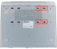
Firstly, you’ll need to locate and remove the screws that secure the NVR’s casing to the base so that you can access the inside of it. Typically, you’ll find two of these screws on the back of the unit and, depending on the NVR model, more on the sides – Do not lose these screws!
Step 2:
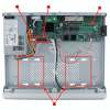
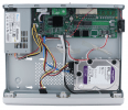
Once inside, your NVR will look something like this. The parts in here you’ll need to identify are the:
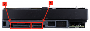
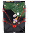
Now look at your HDD – fewer things to identify here:
Step 3:
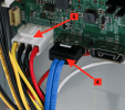
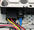
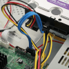
Get your hard drive and NVR connected – You can screw the drive into its bay in NVR first if you wish, but it’s normally easier to wire everything up first. Plug one end of the SATA interface cable into the HDD and the other into the corresponding port on the motherboard, then do the same with the SATA power cable. If the power cable has come already connected to the motherboard, then just plug the other end into the HDD’s SATA power port.
.
Step 4:
You now just need to screw the HDD into the bottom of the NVR via the screw holes located in the HDD and corresponding holes in the HDD bay (insert the screws from underneath the NVR into the HDD inside – it can be a bit fiddly).
Step 5:
Finally, screw the NVR’s casing back onto the base. Your HDD is now installed and ready to be formatted during the initial NVR setup, which is explained in Part 2.
Part 2: How do I complete the basic setup of my Hikvision NVR?
You now need to configure the NVR so that it’s ready to connect to your network. Don’t worry – this is simpler than it sounds. This initial setup is simplest when done on the local GUI, using a directly connected monitor. The following steps walk you through this initial setup process:
Note – Avoid plugging anything into the back of the NVR until instructed to do so in this tutorial.
Firstly, you’ll need to look at the back of your NVR and make sure you can identify the following parts that are needed for this stage:
[1] – PoE (Power over Ethernet) ports (Most Hikvision NVRs have PoE ports which will power any camera via the network cable. Those that do not will require you to connect the camera across remotely, using a separate PoE injector or switch for power.)
[2] – VGA display port
[3] – HDMI display port
[4] – USB port(s) (and mouse – one should come included with the NVR)
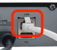
[5] – LAN port (and ethernet cable – Cat5e or Cat6 is fine)
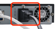
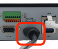
[6] – Kettle power socket (the power lead is included with the NVR)
Now, follow these steps. It is easier if you leave your cameras disconnected until prompted later in this guide:
Step 1:
Plug the kettle plug into the power inlet to connect the NVR to a power supply.
Step 2:
Connect your NVR to a display (this can be any monitor or television) by connecting either an HDMI or VGA cable from the monitor to the corresponding port in the back of the NVR.
Step 3:
Plug your USB mouse into one of the NVR’s USB ports.
Step 4:
Use an ethernet cable to connect your NVR to your local network – Plug one end of the cable into the RJ45 ports into a network access point (such as an ethernet port on your router), and the other into the LAN port in the back of your NVR.
Step 5:
Turn the NVR on and let it boot up. Ignore the beeping noise, it’s completely normal and just the NVR telling you that it isn’t properly configured yet.
You may get a prompt to adjust the NVR’s resolution to match the connected display, click “yes” to view everything in the best resolution supported by your display.
Step 6:
Set your language when prompted.

Step 7:
Set a password for the NVR , as well as a “Channel Default Password”, which will be passed onto any inactive device that is directly connected to the NVR’s PoE ports. We recommend keeping these passwords the same for simplicity’s sake. It’s key that you set a password that the NVR defines as strong and that you remember this password, as resetting the passwords on Hikvision devices can be a hassle that you want to avoid, if possible.
Note – If you have lost your password then please see our guide on How to Reset the Password of your Hikvision Camera/NVR in 5 steps using the SADP Tool

Step 8:
Now set a valid “reserved email” address for the NVR, which Hikvision will use for verification if you need to reset your password.
Step 9:
Next, set an unlock pattern of your choice by using your mouse to draw any shape you like – you will be asked to do this twice to confirm the pattern. This will be used to quickly login to your NVR in the local GUI.
Step 10:
Now, set your time zone, your preferred date format, and date/time.
Step 11:
On the Network Setup page:
Leave the “NIC Type” as it is.
Either leave the “Enable Obtain DNS Server” box ticked, or untick it and use one these recommended public DNS servers.
It is best to leave the “Enable DHCP” box unticked here. Instead, set the “IPv4 Address” of the NVR to an unused IP address on your network, which is within your gateway’s range. Your Gateway will typically be the IP address of your router. E.g. if your router’s IP address is “192.168.1.1”, you’ll want to give the NVR an IP address within the range of “192.168.1.x”, where “x” is any unused address between “2” and “254”.
Note – DHCP can be left on during this stage of the setup to automatically assign your NVR an open IP address if you like, just be sure to turn it off again once your system up and running. To disable it again once set up, just go to:
System/Configuration→ Network → TCP/IP → DHCP Off → Apply
Input the Subnet Mask of your network (typically it’s “255.255.255.0”) and “IPv4 Default Gateway”. If you’re unsure of these, see the below articles which explain how to check what they are and if a particular IP address is available:
How to setup Hikvision IP CCTV System
How-to: How do I find my router and PC’s IP address using a Windows PC?
How-to: How do I find my router and Mac’s IP address using a Mac?
The “Internal NIC IPv4 Address” can be left as it is, this just refers to the NVR’s own LAN address (so Plug and Play cameras will use IP addresses on this range).
Step 12:
You can now stop the annoying bleeping! Select your hard drive(s) from the list and click “Init” to format it, and then “Next” when the formatting has completed.
Note – This will completely wipe the drive, so please make sure that any that are being reused to not have data that you might need on them.
Step 13:
The next page is for the Camera Setup. As mentioned earlier, we recommend connecting any cameras after the NVR setup process has completed, so you can skip this page.
Note – Please see part 4 for the instructions for adding cameras to your NVR after the initial setup.
Step 14:
You will now be taken to the platform access page. Again, skip through and leave this for now.
Note – Please see part 12 for adding the NVR to the Hik-Connect app, which revisits this page.
Step 15:
Finally, you’ll be taken to the Change Password page and given the option to set a new admin password. Ignore this, unless you actually want to change your password. Remember, your admin password is different from your activation password, which you’ll need to use when activating individual cameras on your network.
Click “Exit” and “Yes” on the “Exit Wizard” popup.
That’s the initial setup of your NVR complete. You should now be taken to the NVR’s live view page (you won’t see your cameras until these are connected in Part 4), with your main navigation menu at the top of the screen.
Part 3: How do I find my Hikvision device and edit its network settings?
You probably want to be able to view your camera feeds remotely wherever you are; either in a web browser, the iVMS-4200 software, or the Hik-Connect mobile app. All IP CCTV devices communicate over your LAN (local network) and have a unique location on the network. So, you will need to be able to locate where the device you want to view is and make sure it has the right settings for it to work on your LAN. You will then be able to access the device from a PC or mobile device, and connect it with the rest of your CCTV system.
Please follow the steps beneath to find and correctly set your Hikvision device’s network settings.
Step 1:
The first step is to work out if you need Hikvision’s SADP tool or not. If you only need to discover and access an NVR and some Plug and Play cameras connected directly to its PoE ports, then you don’t need to use it.
If you aren’t using the SADP tool:
Or, on the NVR’s local GUI (Graphical User Interface – when operating the recorder from a connected monitor and mouse), go to:
System → Network → TCP/IP
Here, you can view and change the NVR’s network settings to match your LAN which is explained in step 2 – you can then ignore the rest of the steps.
If you are using SADP:
If your cameras are connected to your LAN, rather than to an NVR’s PoE ports, you will need to install the SADP tool. This scans for all Hikvision devices on your LAN by their MAC addresses. Now, follow steps 2-5 below.
Step 2:
You now need to identify some of your LAN’s settings, which you need to set to match on your devices.
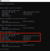
From a Window’s PC, you will need to use the Command Prompt tool to find these.
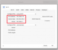
If you’re using a Mac, then you can find these by launching System Preferences, and then going to:
Network → Advanced (make sure your Wi-Fi/Ethernet connection is selected on the LHS) → TCP/IP
Make a note of the following numbers, as you will need to use them when changing your device’s network settings:
IPv4 Address – This is the IP address of the computer that you are using. This address is therefore already occupied, so you will not be able to assign any other devices to this specific address. The digits after the final decimal point indicate where the device is located within the range of your local network, which spans 1-254. You’ll need to change the number after the third period (or full stop/dot) to something that is between “1” and “254” and not already occupied by another device on the LAN.
NB – Please see these guides for instructions on checking if a proposed IP address is occupied:
How-to: How do I find my router and PC’s IP address using a Windows PC?
How-to: How do I find my router and Mac’s IP address using a Mac?
Subnet Mask – This shouldn’t need to be changed on the NVR, it will usually be “255.255.255.0”.
Default Gateway – This is the IP address that’s been assigned to your router. Any device being added to your system needs to be within the range of your gateway in order to be discoverable.
Step 3:
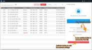
Now, launch the SADP tool again. It should show a list of all the Hikvision devices on your local network and their default network settings. Provided the device is being powered and has a connection to your LAN, then it will show up here. You can also alter the device’s network settings here, and check things like the model number, serial number, the firmware version installed on it.
NB – Remember that any camera that is directly connected to your NVR’s PoE ports will not show up in SADP. This is because the NVR hides any cameras directly connected to it from SADP on its own “subnet”, which is separate from your local network. Don’t worry though, as you won’t need to change the settings for these cameras.
Step 4:
Tick the box beside your device to view and edit the network settings.
If the device hasn’t yet been connected to the network then it will show as “Inactive”. You will be asked to set a password for it when you click the tick-box for it. For more instructions on activating your device, please see Part 6.
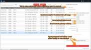
Once activated, ticking the box beside your device will change the network settings in the “Modify Network Parameters” window, so that they match your LAN. You need to make sure that you enter the password for that device before clicking “Modify” for these changes to be saved.
Step 5:
Check that these changes have been reflected in the SADP device table – you may need to wait a few minutes before refreshing. If they have, then you should be to carry on with getting this device connected to the rest of your system.
NB – If you aren’t the camera’s first owner then you will need to perform a hard reset on it. This will reset the device to its inactive factory state so that you can set new password by activating the camera in SADP. Once this has been done, SADP will allow you to modify each network setting edit the network settings to match your LAN so that you can use the device standalone or add it to your NVR remotely.
Part 4: How do I add a Hikvision device to my NVR?
There are a couple of methods for getting your IP camera connected and recording to your NVR:
Plug and Play – This is the most popular and simplest method for smaller setups, as all you need to do is plug your camera straight into the PoE ports in a Hikvision NVR. The NVR will then do the rest of the work. Please note that for Plug and Play to work, the device will need to be inactive or activated with the same password as the NVR.
Remote connection via IP – If you can’t have a wired connection to the NVR, you can instead remotely add a camera on the same network as your NVR to it using the camera’s IP address. For this to work, you will need to make sure to do two things:
1. Replace the power supply that would normally come from the NVR’S PoE ports. Using a PoE switch or injector is usually the best way, as it means you can still add power to the device over the same ethernet cable used for everything else. If not, most will let you connect to a separate PSU.
2. You have connected the camera and NVR to the same LAN and that its network settings are correct for the LAN’s range.
The following steps will guide you through adding new devices using both of these methods. Part 1 covers doing this on the NVR’s local interface (GUI) and part 2 covers how to do this remotely using a web browser.
Method 1 – Via the NVR’s GUI:
Step 1:
On the NVR 4.0 menu at the top of the screen, go to:
Camera → Hover over the desired channel → Click on ‘Edit’ (small icon in the bottom-left corner of channel thumbnail)
Step 2:
An edit window should appear, fill out the fields to add your camera as follows:
Option 1 – Using “Plug and Play”
Connect the camera to the corresponding PoE port number on the NVR (I.e. D1 corresponds to port 1). Then, just select “Plug-and-Play” from the “Adding Method” dropdown, and then click OK to add the camera to that channel – the camera feed should appear after a few seconds to confirm that it’s been picked up.
Note – If you haven’t activated and set a password on the device in SADP, then the IP address should automatically work. The password will be the Activation Password set on your NVR in the initial setup.
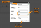
Option 2 – Adding manually via IP
Change the “Adding Method” to “Manual”, which will let you alter the other fields.
Now edit the other fields to point your NVR to the camera’s location on the network, like below:
Adding Method – Select “Manual”.
IP Camera Address – Enter your camera’s IP address here (as explained in the introduction, this will need to match the range of your LAN).
Protocol – Select the device’s manufacturer if it is on the list, or “ONVIF” if it is an ONVIF conformant product.
Management Port – “8000” by default will work fine, or whatever you’ve set the device’s Server Port to if it’s been changed.
Channel Port – This refers to the channel that you want to add the camera to, so leave this as the corresponding number for the channel that you would like to edit.
Transfer Protocol – Set this to “Auto”.
Username – The username you set up when activating the device, usually “admin”.
Password – The camera’s password, which you will have set when it was first activated.
Use Channel Default Password – If you have assigned the NVR and camera the same password during their activation, then you tick this box. This will use the NVR’s password to add the camera and will save you from entering it again in the future.
Enable IP Camera Time Sync – Tick this, as it means the camera will synchronise with the time set on the NVR.
Use Default Port – You can leave this unticked, as you have specified the management port already.
Verify Certificate – Leave this box unticked too.
Click OK to save your changes, the NVR should pick the camera up after a few seconds and show the feed on that channel’s thumbnail to confirm this.
Step 3:
To rename the camera, go to:
Camera → Display
Then, select the camera’s channel from the dropdown, and use the field below to set a new name.
Click “Apply” to save your changes.
Step 4:
You may want to rearrange the Live View screen to show the new camera on a particular tile. To do this, first, go to:
System → Live View → View
Then, select the output port for your connected display that you would like to show the camera on, click on the selected tile and then double-click on the new camera to add it to that tile.
You can select different layout options, or create a customised layout using the toolbar at the bottom of the page.
Click “Apply” to save the new layout.
To check the new layout, launch “Live View” using the NVR’s main menu, and then select that layout using the toolbar in the bottom right-hand corner.
Method 2 – In a web browser:
Step 1:
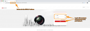
Browse for NVR’s IP address in a web browser, and log in with your username and password for it.
Step 2:
Now, navigate to:
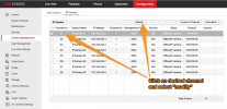
Configuration → System → Camera Management → IP Camera
You’ll be shown a table of all the NVR’s channels, showing which are occupied by cameras, and which aren’t.
These channels normally correspond to the same-numbered PoE ports on the back of the NVR.
Click on the channel that you want to add your device to, and then the “modify” button above the table.
Step 3:
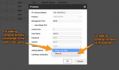
A window titled “IP Camera” should appear allowing you to change the “Adding Method” and “IP Camera Address” set for that channel.
If you haven’t already, you will need to make sure that the camera has a valid IP address and correct network settings for your LAN’s range.
Option 1 – using “Plug and Play”:
You just need to make sure that:
Note – If you haven’t activated and set a password on the device in SADP prior to connecting it to the NVR, then the IP address should automatically work and the password will be the “Channel Default Password” set on your NVR in the initial setup (see step 7 here)
Option 2 – Adding manually via IP:
Change the Adding Method to Manual, which should let you alter the other fields.
Now alter the other fields to point your NVR to the camera’s location on the LAN, like below:
IP Camera Address – Insert the camera’s IP address
Protocol – Select the brand of your camera here, or ONVIF if it is ONVIF conformant and the manufacturer doesn’t appear in this list.
Management Port – This is the camera’s network port, which is usually 8000 by default.
Username – The username that you set for the camera, which is usually “admin”.
Password – The password assigned to the camera upon activation in SADP. If you have automatically activated the camera by plugging it into your NVR’s PoE ports, this will the the “Channel Default Password” set during the NVR setup.
Confirm: Retype this password.
Transfer Protocol: This is fine for you to leave as “Auto”.
Green ticks should appear beside each field to indicate that what’s inside is valid. Once completed, you can click “OK”:
The “Security” column should be “Strong” and “Status” should change to “Online” on the “IP Camera” page – If they do, then you’re finished, just return to the Live View page to check that the camera’s feed is now visible.
Note – Clicking the “Start All Live View” button in the toolbar at the bottom of this page will show all of your working cameras feeds at the same time.

