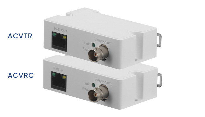
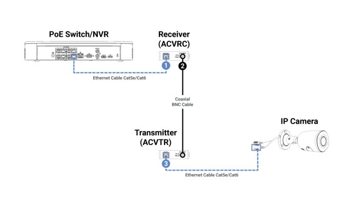
Easily Connect IP Cameras Over Existing Coaxial Cabling This article will walk you through the easy steps to connect Lorex’s Coaxial to Ethernet Converter, a plug-and-play solution for connecting and powering IP cameras over existing legacy coaxial cabling. If you have a camera security system that is wired for coaxial and you cannot run Ethernet, you can connect our Coaxial to Ethernet Converter Kit. This enables upgrading your analog system to IP while still using existing coaxial cabling. The converters are small, lightweight, easy to install, and do not need to be connected to an additional power adapter
Upgrade your DVR Security System
If you have a camera security system that is wired for coaxial and you cannot run Ethernet, you can connect our Coaxial to Ethernet Converter Kit. This enables upgrading your analog system to IP while still using existing coaxial cabling. The converters are small, lightweight, easy to install, and do not need to be connected to an additional power adapter. There is no need to run new cabling, simply plug the converters in. Send data and power over coax up to 900 m (2,952 ft) reach (performance and supported length are subject to transmission coaxial cable and coupler quality). This is a cost-effective and useful solution for legacy DVR upgrades and future expansion.
Coaxial to Ethernet Converters
To upgrade your wired system to an NVR with IP security cameras, you will need:
or
Features:
Easily Connect IP Cameras Over Existing Coaxial Cabling
Also Read : How to use Webcam on Surveillance Station on QNAP NAS?
Installing your Coaxial to Ethernet Converters
Safety Precautions
Please read the following safeguards and warnings carefully before using the product in order to avoid damages or losses:
![]() WARNING: Do not use power line other than the one specified. Please use it properly. Otherwise, it may cause fire or electric shock.
WARNING: Do not use power line other than the one specified. Please use it properly. Otherwise, it may cause fire or electric shock.
Installation
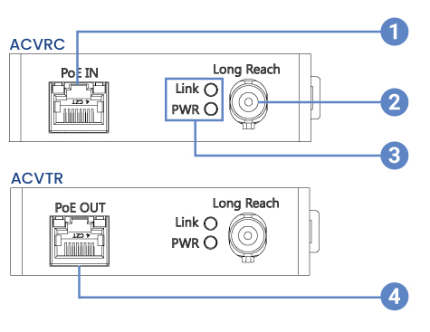
Product Overview & LED Indicators
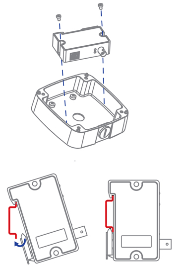
Mounting
The Coaxial to Ethernet Converter supports two installation modes: junction box or it can support DIN rail mount.
Note: Supports slide width of 28 mm (1.1”)
For full mounting instructions, please refer to the junction box’s Quick Start Guide on Lorex’s support page.
Product Specifications
PoE Power Supply Specifications (RG59 Coaxial Cable)
ePoE switch supply voltage 48V. / RG-59, max. DC resistance < 5 Ω / 100 m (328 ft)
ePoE switch supply voltage 53V. / RG-59, max. DC resistance < 5 Ω / 100 m (328 ft)
4K IP Wired Dome Security Camera with Smart Deterrence: Installation
This article provides instructions on how to install and connect 4K Smart Deterrence IP Dome Camera with Smart Motion Detection Plus (E893DD Series) to the NVR.
Before Installing
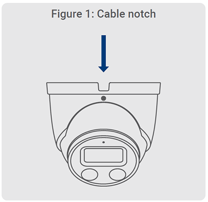
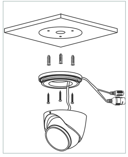
Installing 4K Smart Deterrence IP Dome Camera
Connecting 4K Smart Deterrence IP Dome Camera
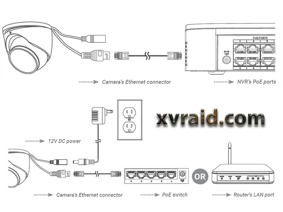
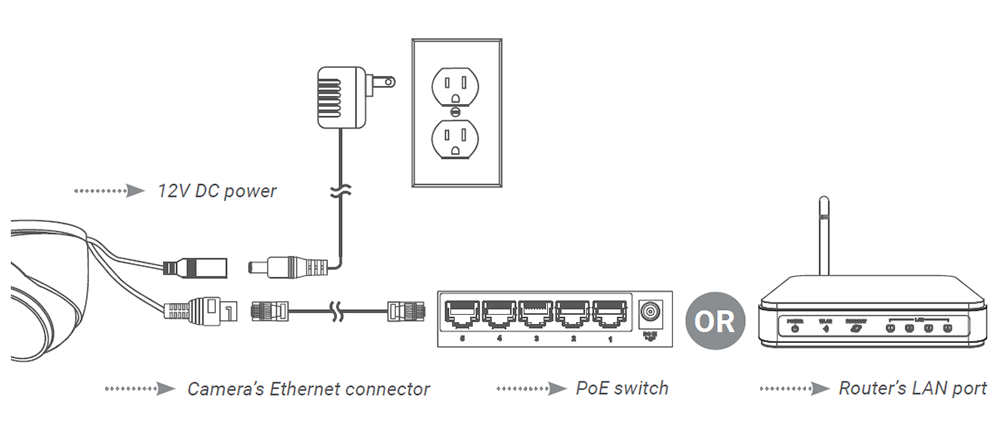
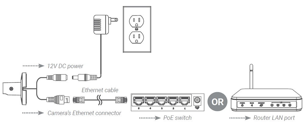
Connect the cameras and cables to your NVR using one of the following two setup methods.
1. Connect cameras directly to the NVR (recommended)
Connect the Ethernet cable to the camera and then connect the other end of the Ethernet cable to the NVR’s PoE ports. The camera may take a minute to power on after being connected.
Note: A 12V DC power adapter (model#: ACCPWR12V1, not included) is only required if connecting the camera’s Ethernet cable to a router or switch that does not support PoE.
Notes:
2. Connect cameras to a PoE switch or router on your network (not included)
Connect the Ethernet cable to the camera and then connect the other end of the Ethernet cable to a router or switch on your network. See your NVR manual for details on connecting the camera to your NVR using a router or switch.
Using the RJ45 cable gland (optional)
The pre-attached RJ45 cable gland covers both the camera’s Ethernet connector and the RJ45 plug to provide weather-resistance and protection from dust, dirt and other environmental contaminants.
To use the RJ45 cable gland, twist the RJ45 cable gland barrel securely onto the camera’s Ethernet connector.
Tip: The RJ45 cable gland is weather-resistant. Seal the cap with silicone and/or electrical tape for additional sealing if it will be exposed to precipitation regularly.
Cable extension options
You can extend the Ethernet cable run for your camera up to 300ft (91m). To extend the cable run beyond 300ft (91m), a switch will be required (sold separately). Use an RJ45 coupler or a network switch (not included) to connect male ends of Ethernet cables together. We recommend using UL CMR approved cables available at lorex.com.
4K IP Wired Dome Security Camera with Smart Deterrence: Getting Started
This article provides instructions on how to setup the 4K Smart Deterrence IP Dome Camera with Smart Motion Detection Plus (E893DD Series).
Important Installation Guidelines
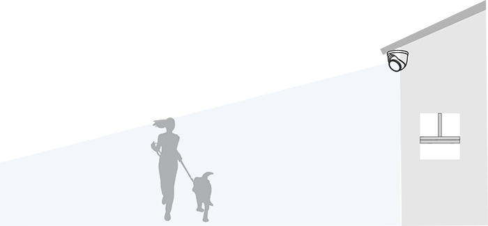
The optimal installation location, including the height and angle of your camera, will depend on the type of detection settings that you want to enable. Since the optimal angle for person and vehicle detection is different from the optimal angle for face detection, you will need to select one approach.
Note: You cannot enable both face detection and person and vehicle detection at the same time.
Based on your detection preference choose between:
1. Optimizing person and vehicle detection accuracy
Accuracy of person and vehicle detection
Accuracy will be influenced by multiple factors, such as the object’s distance from the camera, the size of the object, and the height and angle of the camera. Night vision will also impact the accuracy of detection.
2. Optimizing face and mask detection accuracy
Note: Facial recording without consent is illegal in certain jurisdictions. Lorex Technology does not assume liability for any use of its product that fails to conform with local laws.
High accuracy Vs. low accuracy face detection
Accuracy will be influenced by lighting conditions and the distance/angle of a person’s face to the camera.
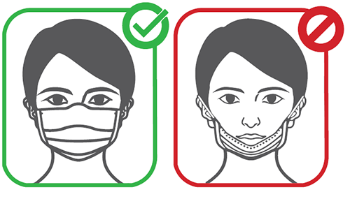
Mask detection
With face detection enabled, you can set the alarm type to detect if a person is not wearing a mask. A person not wearing a mask or improperly wearing a mask will be captured in the face preview sidebar and a notification will be sent through the Lorex App.
For full instructions on installing and connecting the 4K Smart Deterrence IP Dome Camera to the NVR, visit Installing 4K Smart Deterrence IP Dome Camera.
4K Ultra HD Smart Deterrence IP Camera: Installation Guide
This article provides instructions on how to install and connect 4K Ultra HD Smart Deterrence IP Camera (E893AB Series) to the NVR.
Before Installing
Installing 4K Ultra HD Smart Deterrence IP Camera
Connecting 4K Ultra HD Smart Deterrence IP Camera
Connect the cameras and cables to your NVR using one of the following two setup methods.
1. Connect cameras directly to the NVR (recommended).
Connect the Ethernet cable to the camera and then connect the other end of the Ethernet cable to the NVR’s PoE ports. The camera may take a minute to power on after being connected.
Note: A 12V DC power adapter (model#: ACCPWR12V1, not included) is only required if connecting the camera’s Ethernet cable to a router or switch that does not support PoE.
Notes:
2. Connect cameras to a PoE switch or router on your network (not included).
Connect the Ethernet cable to the camera and then connect the other end of the Ethernet cable to a router or switch on your network. See your NVR manual for details on connecting the camera to your NVR using a router or switch.
Using the RJ45 cable gland (optional)
The pre-attached RJ45 cable gland covers both the camera’s Ethernet connector and the RJ45 plug to provide weather-resistance and protection from dust, dirt and other environmental contaminants.
To use the RJ45 cable gland, twist the RJ45 cable gland barrel securely onto the camera’s Ethernet connector.
Tip: The RJ45 cable gland is weather-resistant. Seal the cap with silicone and/or electrical tape for additional sealing if it will be exposed to precipitation regularly.
Cable extension options
You can extend the Ethernet cable run for your camera up to 300ft (91m). To extend the cable run beyond 300ft (91m), a switch will be required (sold separately). Use an RJ45 coupler or a network switch (not included) to connect male ends of Ethernet cables together. We recommend using UL CMR approved cables available at lorex.com.
