Hikvision Full installation guide, Hikvision is committed to serving various industries through its cutting-edge technologies of machine perception, artificial intelligence, and big data, leading the future of AIoT: through comprehensive machine perception technologies, we aim to help people better connect with the world around them.
with a wealth of intelligent products, we strive to identify and satisfy diverse demands by delivering intelligence at your fingertips; through innovative AIoT applications, we are dedicated to empowering every individual to enjoy a better future by building an intelligent world that is more convenient, efficient and secure.
Hikvision ‘How To’ Tutorials
Here you can find all of the Hikvision-related ‘How-To’ Tutorials that the team at use-IP have created
How Do I Configure the Camera’s Onscreen Display Text?
All Hikvision users will have seen that when you first log in to a camera the live view will have overlayed text stating the date & time and the default name of the camera “IPcamera 01”, depending on your requirements you may want to change some or all of this overlay text and below is the instruction for how to do that.
Method 1 – In a Web Browser
Log in to the camera and go to Configuration > Image > OSD Settings
.
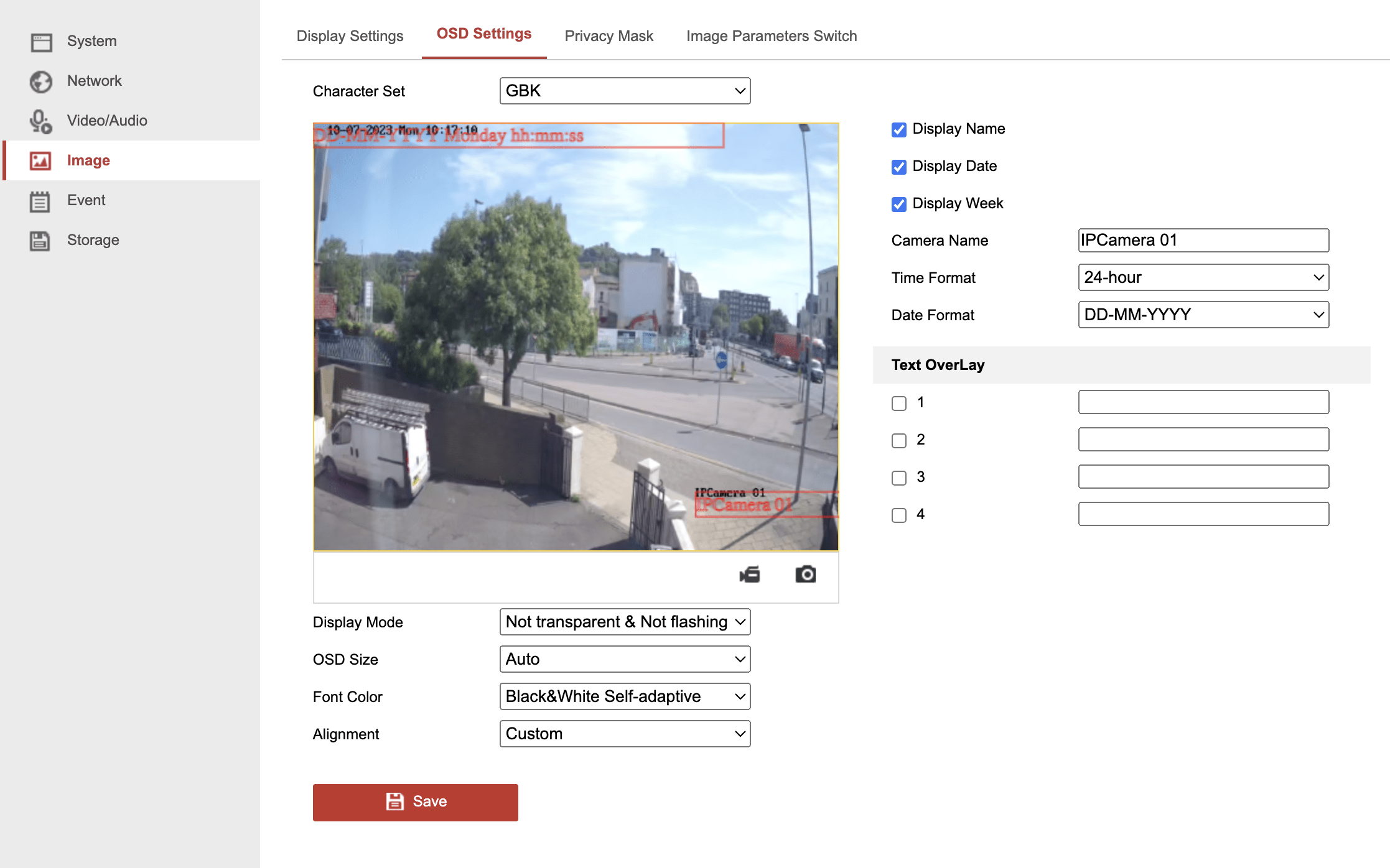
Below we will take you through each of the above settings and what they do:
Character Set – This lets you select the characters/language the OSD settings use, by default all UK stock will come with this set as GBK for English characters but if you are a European customer and you want to enter special characters from your particular language (e.g. é, ü, ç, etc…) you can switch it to EUC-KR to access those characters (do this will require the camera to reboot).
Display Name / Date / Week – These tick boxes let you show/hide the camera name (Display Name), the current date (Display Date), and the day of the week (Display Week)
Camera Name – This box lets you set the displayed name of the camera, it will also change the name of the camera shown in the System menu and if added to an NVR it will change the name shown in the live view camera list and the Camera Management list.
Time Format – This dropdown lets you select how the time appears in your live view, either 24-hour format (00:00 – 23:00) or 12-hour format (00:00 – 12:00)
Date Format – This dropdown lets you select how the day, month, and year are displayed. Your options are DD/MM/YYYY (UK format), MM/DD/YYYY (US format), and YYYY/MM/DD (Chinese/International Standard format). You also have the option of separating the day, month, and year with either a “–” or a “/“.
Text OverLay – On most cameras, you should have the option to add up to 4 additional text overlays to the live view. You can use all of them or none of them depending on your requirements.
Display Mode – This dropdown lets you choose how the text behaves on screen, by default it will usually be set to Not Transparent & Not Flashing which means the text will obscure objects/people behind it and it will be onscreen all the time. You have the option to change it to one of the following – Transparent & Flashing / Transparent & Not Flashing / Not Transparent & Flashing – When set to transparent the text will become semi-transparent so that you can see objects/people behind the text and if set to flashing the text will flash on & off screen every few seconds (there are no controls for the flashing duration).
OSD Size – Technically this setting should adjust the size of the OSD text but we’ve found that when changing it there was little change to the text and so we would just stick to the default Auto option because this will allow the text size to adapt based on where you are viewing the live image (e.g. whether a small phone screen or a large TV).
Font Color – This dropdown lets you select the colour used by the OSD text, by default the camera will use Black&White Self-adaptive which means the text colour will automatically switch between black & white based on what is behind the text (e.g. if a person walks through the text) and for high-security sites, this can be an important feature for using the footage in court because the adaptive text shows that the image/text has not been manipulated in post. If the scenario requires it you can select Custom which will allow you to pick the text colour from a standard colour table.
Alignment – Again like OSD size this setting doesn’t appear to have a huge impact so we would just leave it as the default Custom and you can adjust the positioning/alignment of the OSD text by dragging the red boxes around the live view window above (these red boxes are only for adjusting the text position and will not appear on the actual live view image).
Hikvision Full installation guide
Read More : How To basic setup of Hikvision NVR
.
Method 2 – Via the NVRs GUI
.
You can access similar OSD settings from the NVR by going to Camera > Display and selecting the camera you want to configure.
.
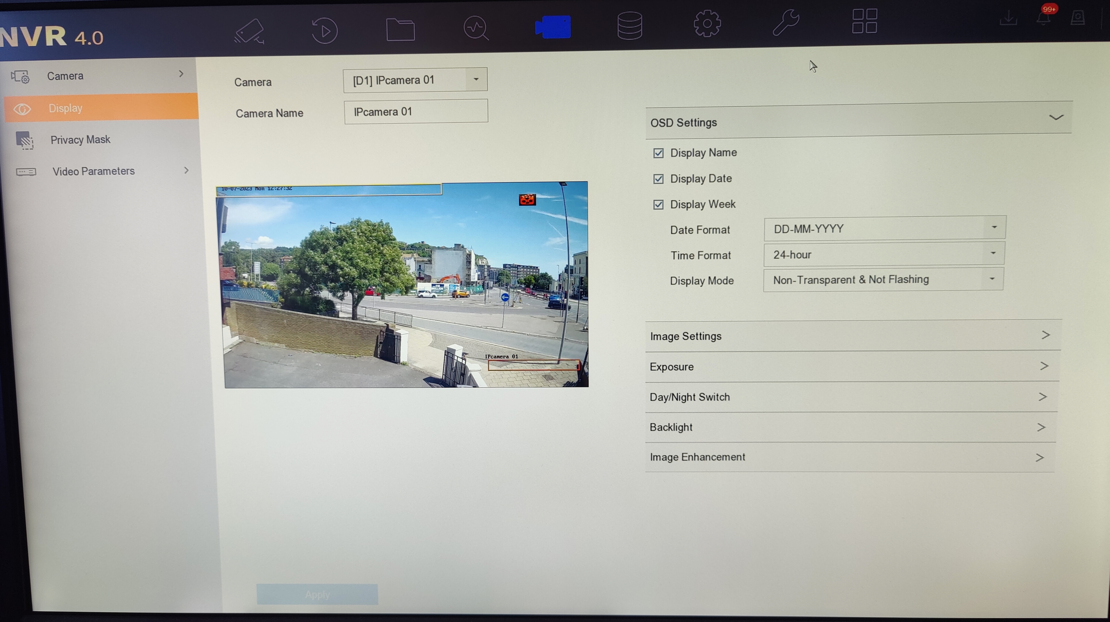
Although, as you can see from the above screenshot you won’t get all the settings that can be found by logging into the cameras directly.
How do I set up ‘Rotate Mode’ on my Hikvision IP camera for the best picture in narrow scenes?
Corridor mode is a really useful feature available on many different CCTV cameras that can be utilised to effectively monitor a space that is more vertical, rather than horizontal, in shape. These types or areas include hallways, pathways, staircases, shopping aisles, tunnels and roads. When installing and viewing a CCTV camera, you want the image frame to include as much of the area of interest, while cutting out as much of the redundant areas, like the walls and ceiling, as possible.
Corridor mode allows you to rotate the camera’s lens and the video image 90 degrees so that it’s in a portrait, rather than a landscape format. As a result, you can use the camera to really focus on those areas of interest of within in your frame changing the image’s aspect ratio from 16:9 to 9:16 to suit narrow monitoring settings. The image below is taken from a camera making use of this function and illustrates the differences between the corridor and standard settings:
.
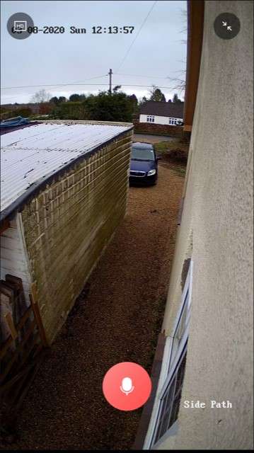
This guide will show you how to utilise corridor mode on Hikvision’s three most popular camera types: domes, turrets, and bullets. I will cover how to activate this useful setting in iVMS-4200, a browser, and locally through your NVR’s GUI so that, irrespective of your setup, this guide should be of help.
Part 1: How do I activate the corridor mode function in my camera’s settings?
We suggest getting your camera set up on your network and activating corridor mode in its settings before you try to rotate and position the lens. This way, you can use the live video stream, in the correct aspect ratio, to point the lens in your optimum direction. Positioning the lens often involved a bit of trial and error to get the best result specific to your space.
.
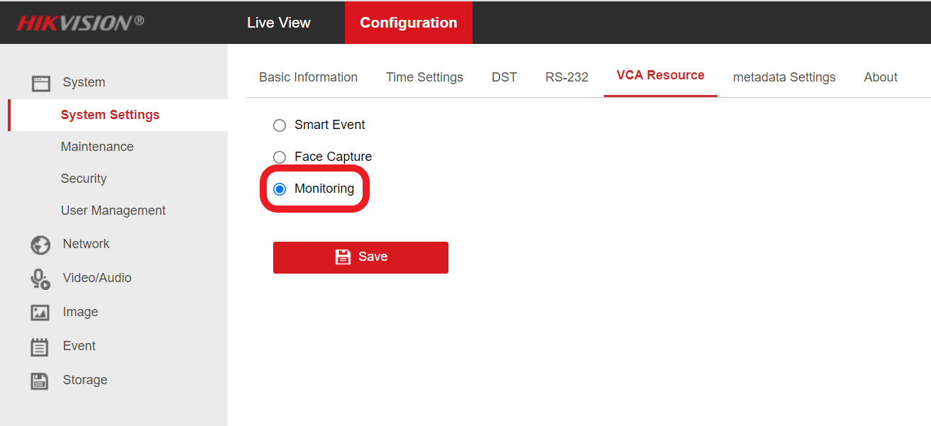
Note – For the G2 AcuSense models, you will need to connect to the camera directly in a web browser and change the “VCA Resource” to Monitoring Mode by navigating to:
Configuration → System→ System Settings → VCA Resource
.
Please note that this will disable most of the smart event options, leaving only Scene Change Detection available to use.
Locally (via a monitor connected to an NVR):
If your camera is connected to an NVR, then you can easily configure corridor mode in the setting through the NVR’s GUI menu. Just Navigate to:
Menu > Camera > Image
Pick your camera from the top drop-down box beside Camera and then select “Clockwise 270 degrees” in the Enable Image Rotation box
Then, just click Apply
Through iVMS-4200:
If you’re not using an NVR, or don’t have easy access to your NVR’s GUI, then an option is to use iVMS-4200 to set up corridor mode by accessing the camera directly.
To do this, first, you’ll need to navigate to:
Menu > Device Management
.
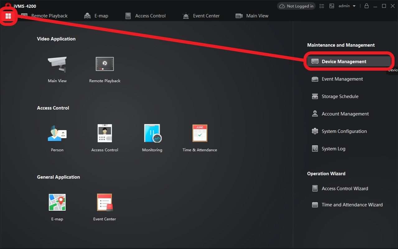
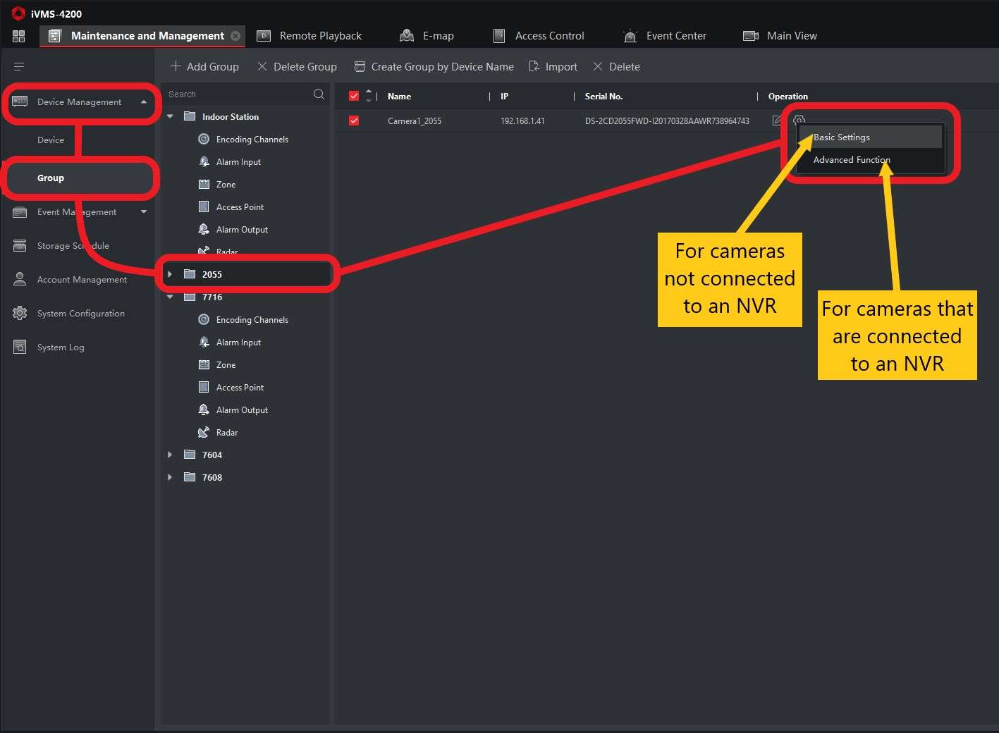
Find your camera in the device list. If accessing a camera connected to an NVR, you’ll need to open your NVR within the Group section of the Device Management screen and then the particular camera within the NVR’s device list.
Click Configure (the small cog) on your camera.
If your camera isn’t connected to an NVR, then open Basic Settings, if it is then open Advanced Function.
.
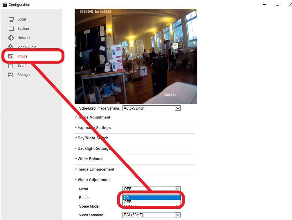
In the popup window, open the Image tab in the sidebar. You should then see either a tick-box or drop-down that allows you to turn on Rotate, tick or select ON in the applicable box or drop-down and then Save. The camera view should now have been rotated.
.
.
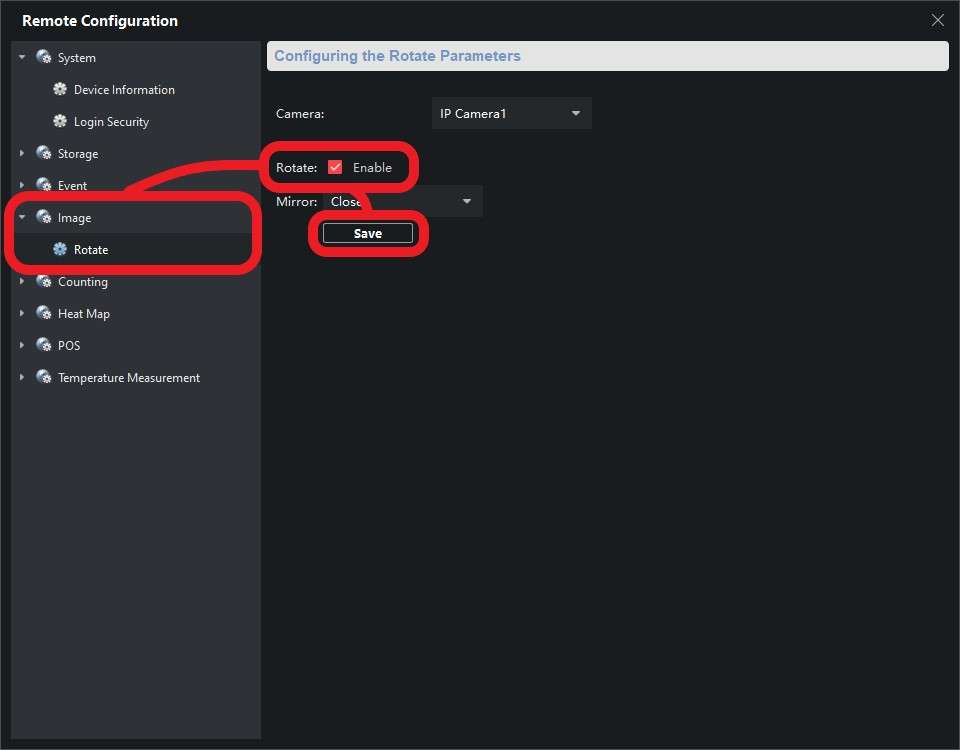
In a web browser:
The other method commonly used to access cameras and NVRs is through a web browser. You will only be able to configure the image rotation settings for a remote camera. The image for cameras connected directly to an NVR cannot be rotated in this menu due to the restricted access to the camera’s settings.
To access your camera in a browser, simply input its IP address into the browser’s address bar and hit enter. You’ll be taken to a login screen, here you’ll need to fill out the username and password combination you created for the camera when you first set it up. If correct, you should be taken to a page displaying the camera’s live video stream.
The process of rotating the camera’s image is relatively similar to that in iVMS-4200, just go to:
Configuration > Image > Video Adjustment > Rotate > On
The setting should be automatically saved, you’ll see a popup in the bottom-right corner of your window confirming this. That’s it!
.
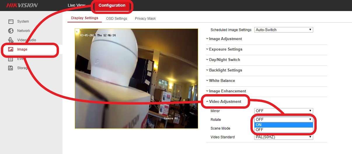
.
.
Part 2: How do I position and rotate my camera’s lens correctly?
Rotating the camera’s image through its settings will rotate the image 270 degrees. To rotate the final video stream to the desired 180 degrees, you will manually need to turn the camera’s lens 90 degrees in the opposite direction as compensation. The entire process allows the rotated image to properly fit a 9:16 portrait aspect ratio. You’ll need to follow the below steps in order to rotate the camera’s lens.
For Domes / Mini Domes:
Domes and mini domes are the fiddliest type of camera to move and rotate the lens on. You can do this with the camera either installed or taken down. You’ll need to take the outer casing off the dome first to allow you to move the lens inside.
Then, loosen the locking screw located to the right of the lens rotate to allow you to move the lens and bracket. Now twist the lens bracket (the bit that can turn surrounding the lens, see the picture below) 90 degrees anti-clockwise, so that the gap in it is in the 3 o’clock position. You should see the “90” marker in the middle of the gap once in this position.
Now twist the lens (see the picture below) 90 degrees anti-clockwise, holding the lens bracket in place while doing this helps, so the “90” marker is at 12 o’clock and the “0” marker is in the 3 o’clock position. It may take a bit of wiggling and feel unnatural but the lens will move to this position, you won’t break anything!
.
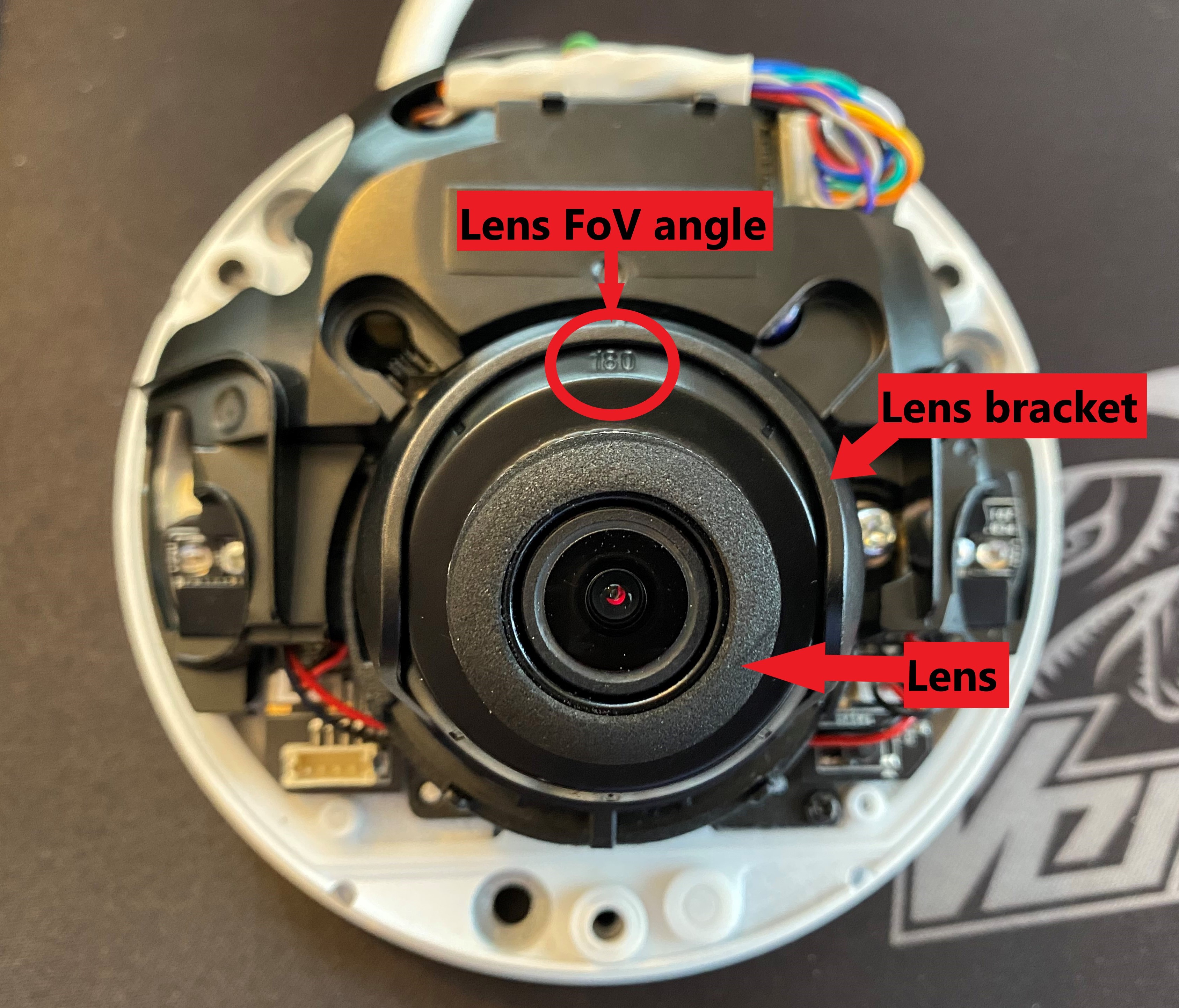
Finally, rotate the lens bracket 90 degrees clockwise so that the gap is at 6 o’clock, and then move the lens so that is fits into this gap, so it looks like the picture below. This next stage takes a bit of trial and error on your part to get your desired camera view.
You’ll need to fiddle around with the lens while looking at the camera’s live stream to ensure it is straight and something you’re happy with. Viewing your stream through iVMS-4200 or Hik-Connect is best as you can look at the image and remotely while fiddling with the lens position at the same time.
.
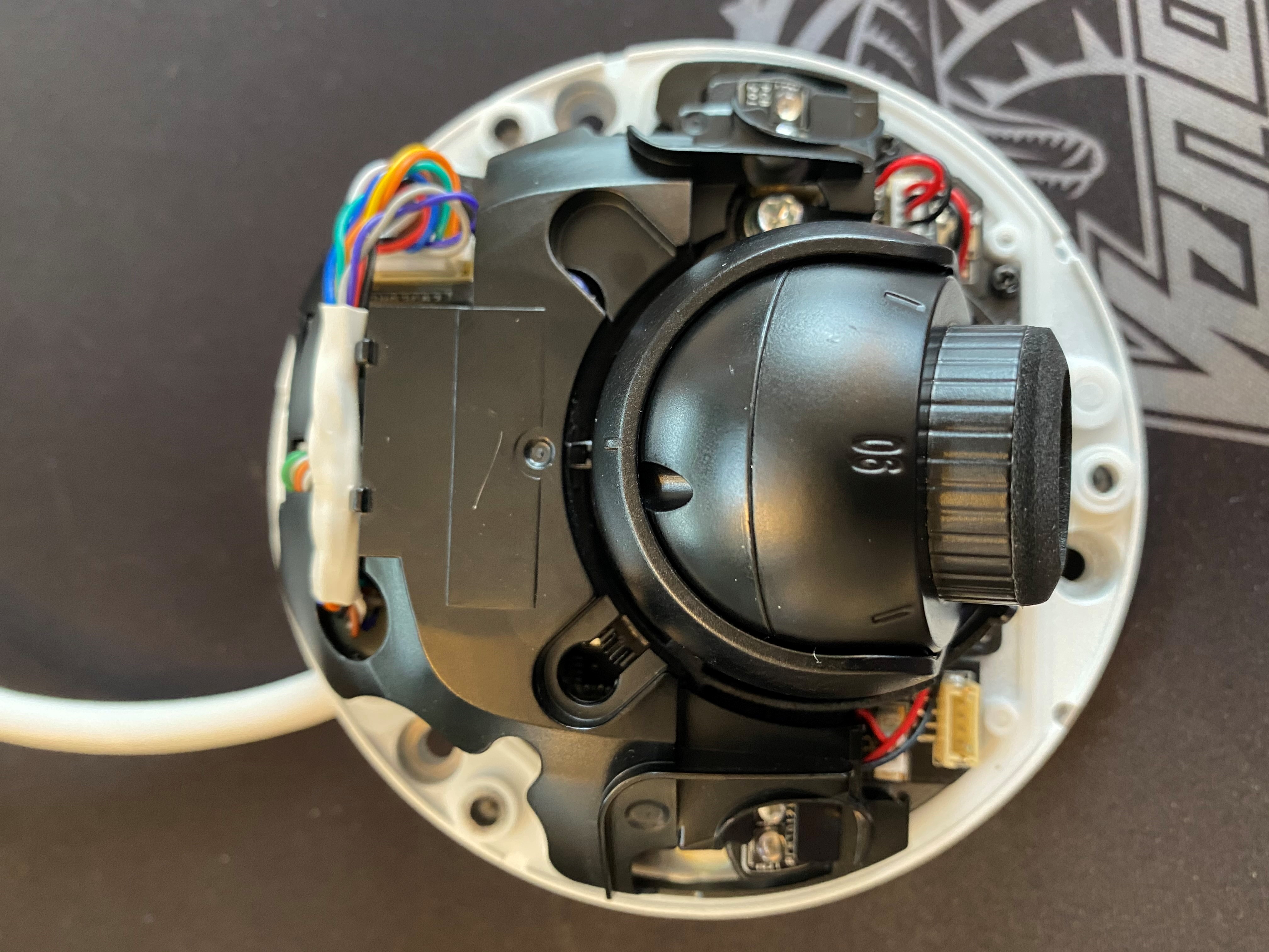
For Turrets:
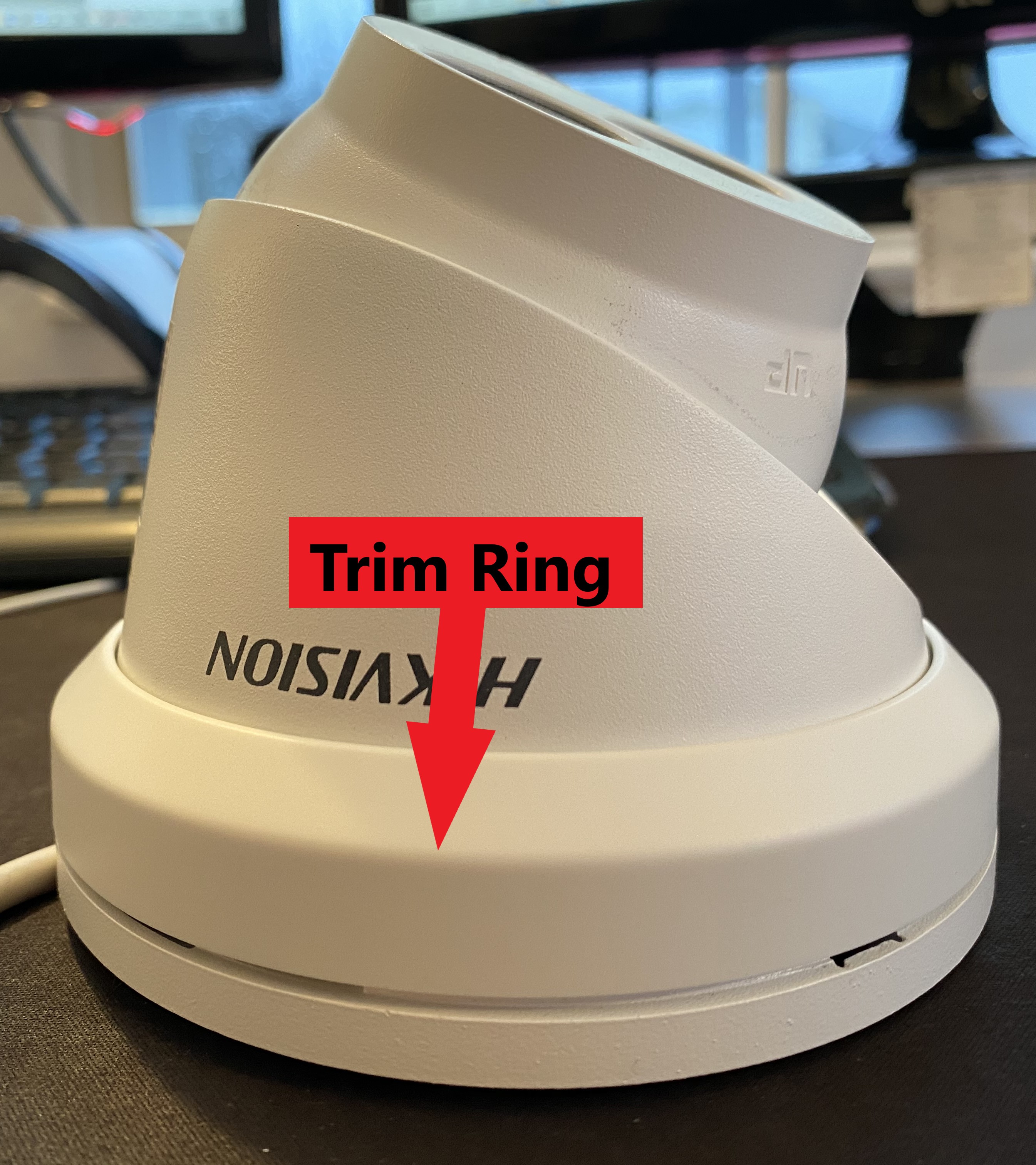
Rotating the lens on a turret camera is a slightly more straightforward process. First, you’ll need to remove the trim ring (shown in the picture below) by twisting it anti-clockwise and lifting it off the base of the camera.
.
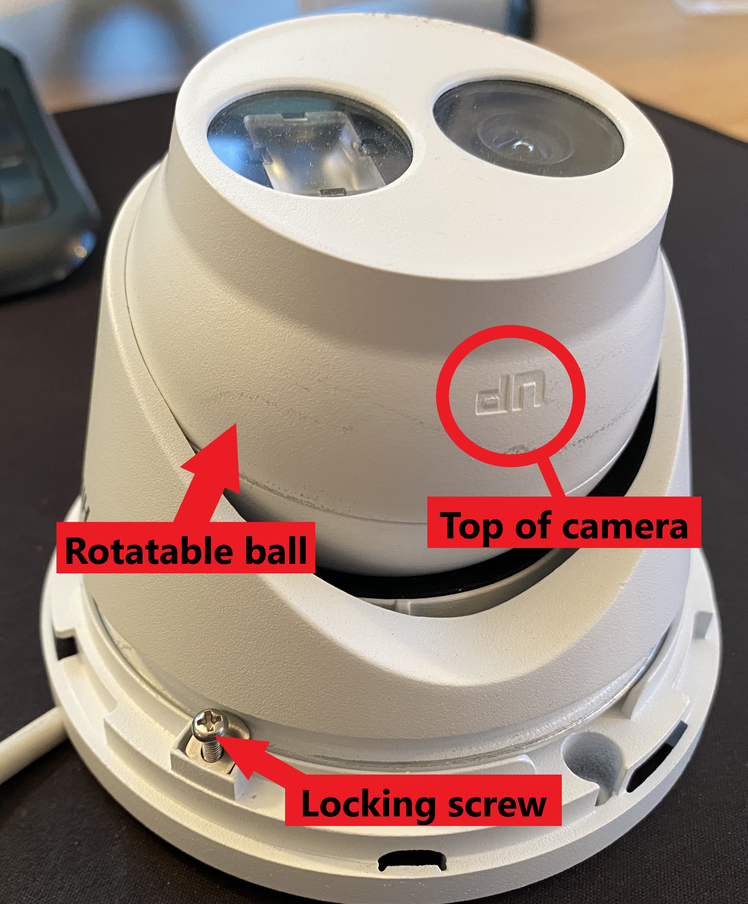
This should expose the locking screw, you’ll need to loosen this using a Phillips-head screwdriver enough for Turret’s ball to be rotated. You shouldn’t need to take the screw out entirely. All these parts are labeled in the picture below. The “UP” marker on the ball indicates the top of the camera.
You’ll now need to rotate the ball 90 degrees anti-clockwise so that this marker moved from the 12 o’clock to 9 o’clock position. Now, tighten the locking screw back up and replace the trim ring to its original position. The lens should now be appropriately rotated.
.
For Bullets and Mini Bullets:
The camera models that allow for the easiest rotation of their lenses are bullets and mini bullets.
It is important to note that the sun shield on these cameras cannot be moved to be above the lens when rotated, which presents a drawback so using them for corridor mode.
The sun shield will sit to the side of the rotating lens in this case so you’ll need to make sure that you shelter the camera somewhat (such as under the eaves of a roof) if setting a bullet or mini bullet for corridor mode.
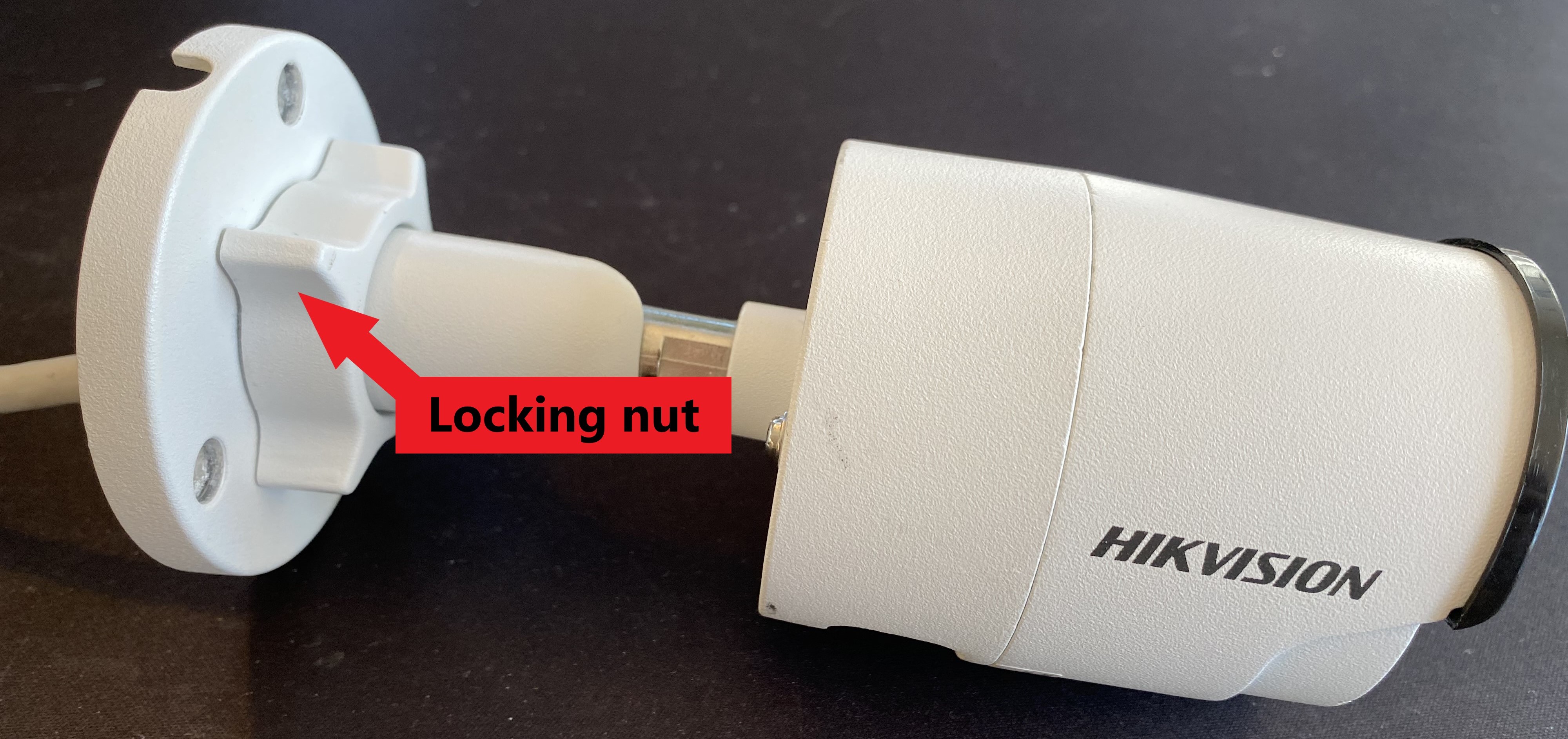
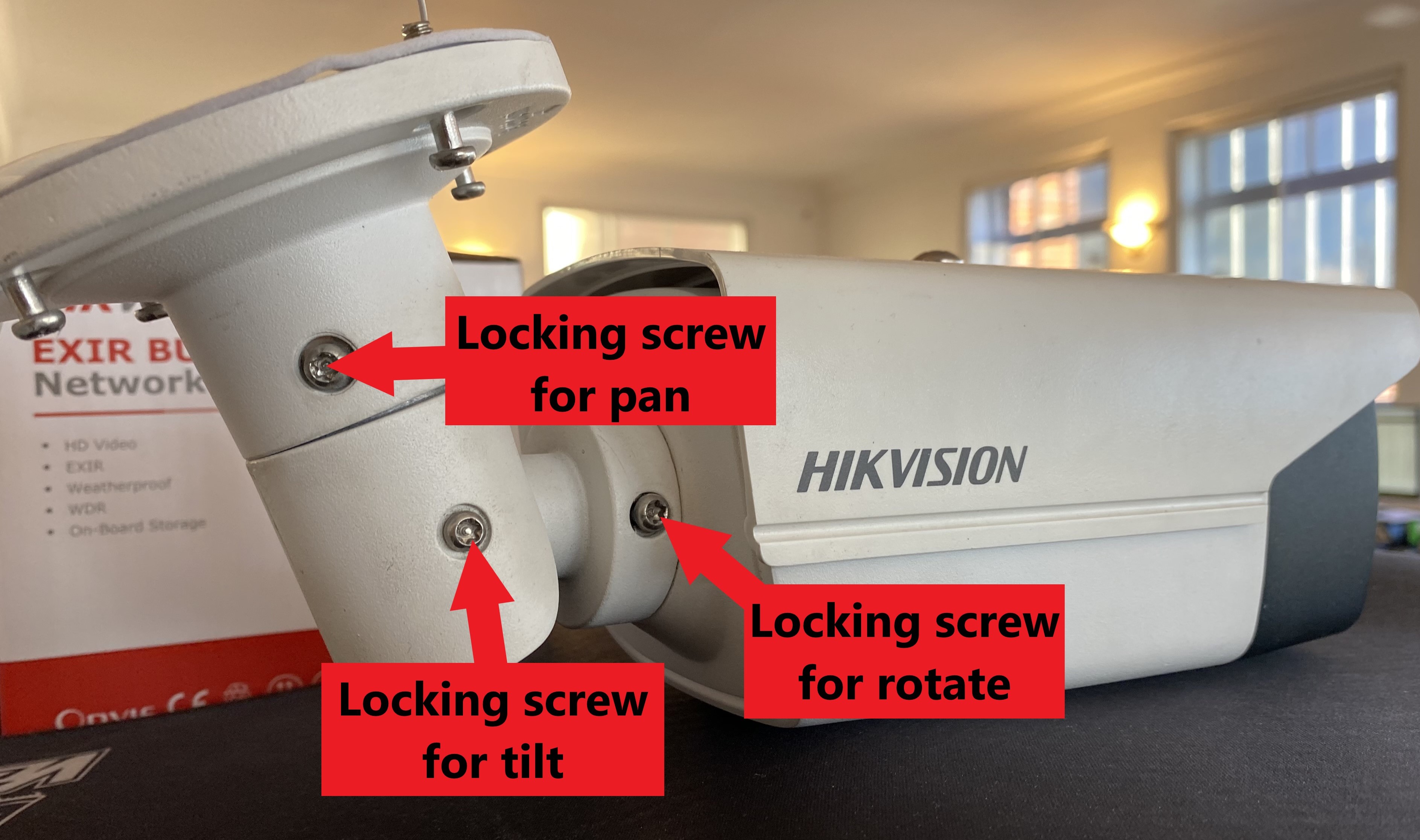
Mini bullets have a locking nut (shown below) at the end of their base which will allow you to rotate the camera when loosened. Larger bullets will require you to loosen the locking screw, which is the screw furthest to the right of the base if looking at them (shown below).
Once you’ve loosened the locking screw/nut as appropriate, rotate the main body of the camera 90 degrees anti-clockwise, so that the sun shield is in the 9 o’clock position. This will rotate the lens. Once you’ve done this, tighten the screw or nut again to secure the camera in its newly rotated position.
.
.
Part 3: How do I change the layout of my camera streams to accommodate for corridor mode?
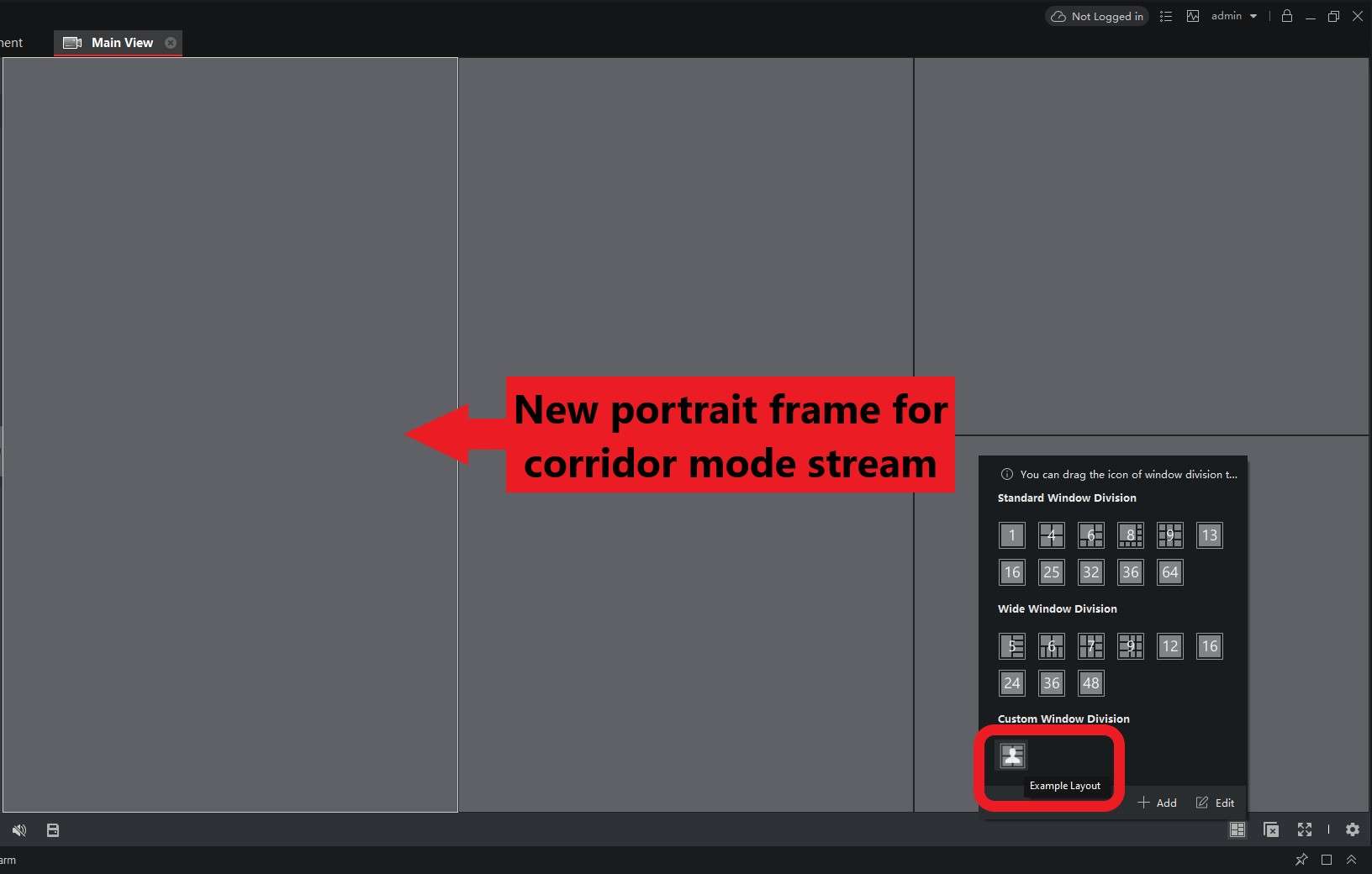
Once your camera is all set up in corridor mode, you’ll want to be able to adjust the way that you view the grouped cameras to avoid the camera’s live stream being reduced in size to fit the standardised landscape 16:9 frame. This is easily done by simply merging two of the landscape frames to make a portrait, 9:16 frame to which you can dedicate your camera.
This custom view layout can be set up in an NVRs local GUI and in iVMS-4200. Please see the guides below for an explanation on how to customise your stream layout to accommodate corridor mode.
In iVMS-4200:
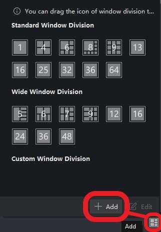
Click on the small icon made up of several small boxes at the bottom of your Main View screen in the program, this should bring up the window division page. Click Add to create a Custom Window Division.
.
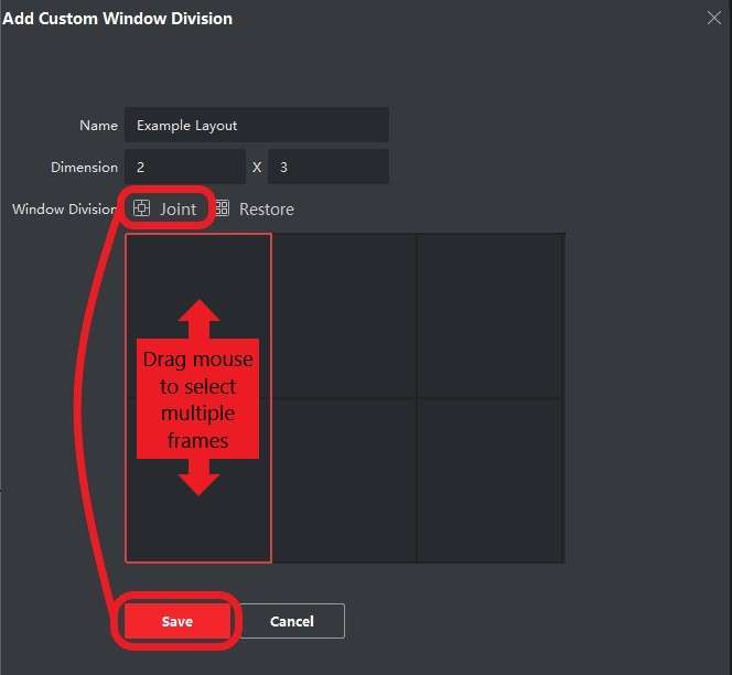
In the Add Custom Window Division popup, set the name and dimensions of your new stream layout as desired.
Now, click and drag your mouse over the two frames you want to merge to select them both. Once they’ve both been highlighted by a surrounding red box, click Joint to merge them. Now click Save.
.
Once back in the Main View, click on the Window Division icon in the bottom right-hand corner again and select your new custom layout from the list. Your new stream layout should load ready for you to assign the individual cameras to.
.
Locally through your NVR’s GUI:
Please Note – This option is only available on NVRs that are running Version 4 firmware. There is not currently an option to customise your stream layout on K-Series recorders. If you’re running Version 3 firmware then your only option is to configure your layout as per above in iVMS-4200.
It’s also useful to be able to customise the stream layout as viewed directly from your NVR’s GUI as this is many people’s preferred method for observing and configuring their camera feeds.
To do this, firstly, you’ll need to navigate to:
Configuration > Live View > View > Set Custom Layout (small cog in bottom-left hand corner)
.
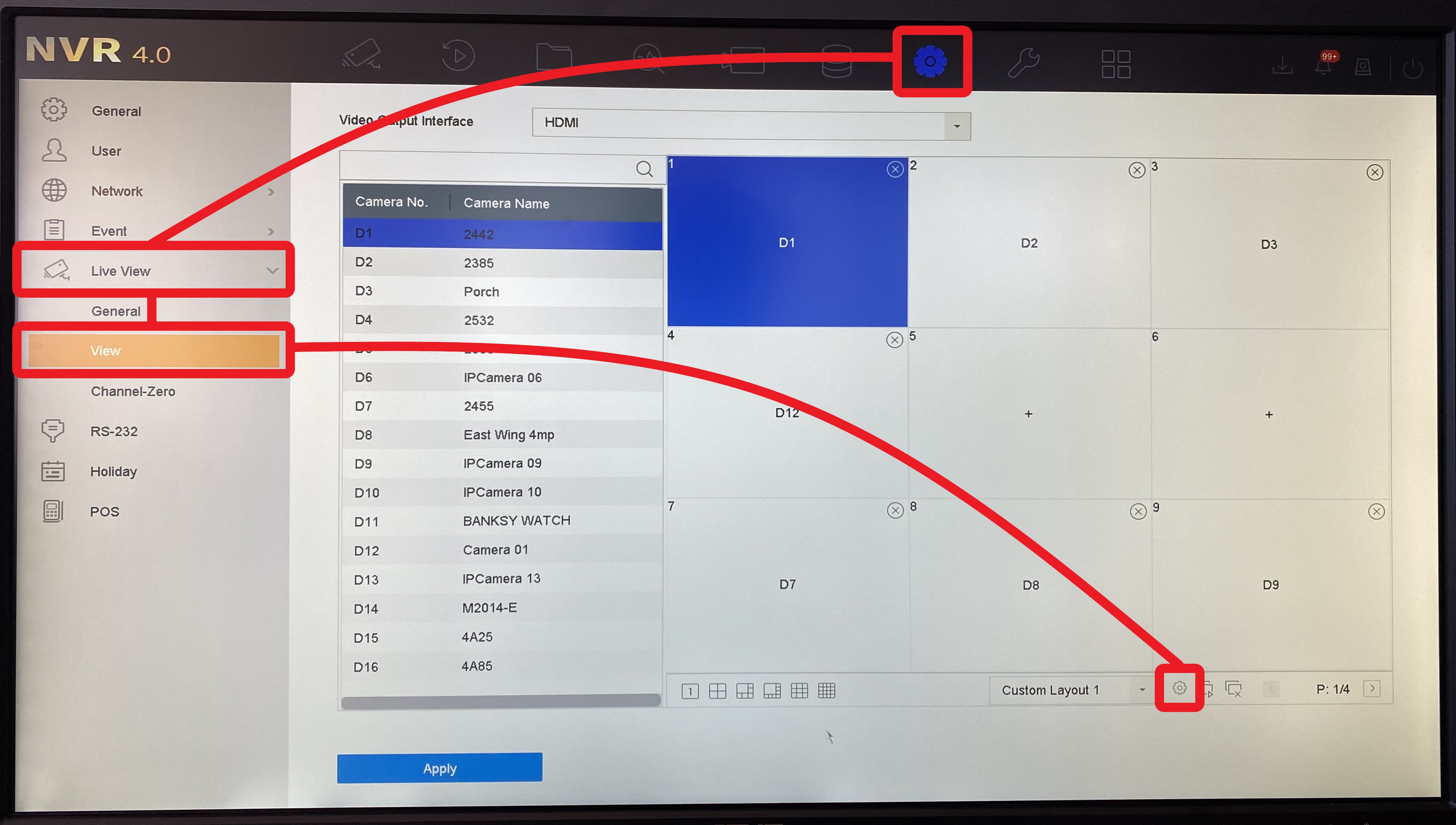
In the Custom Layout Configuration popup, set the name and dimensions of your new stream layout as desired. Now, click and drag your mouse over the two frames you’re going to merge and click the Joint button in the top toolbar, followed by Save.
.
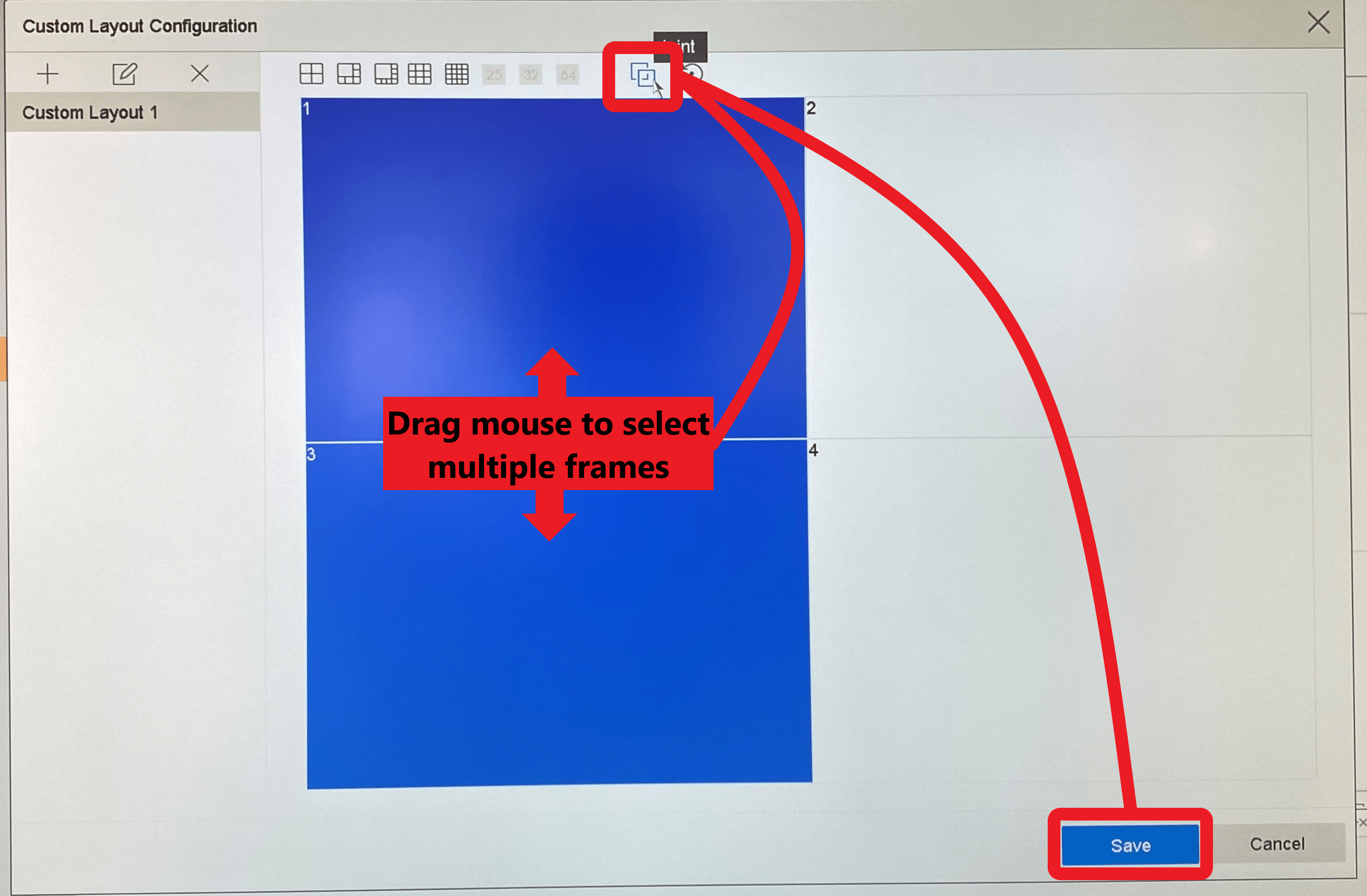
Once back in the Live View, click on the Split button in the bottom-right hand corner of your screen. Then, select your new custom layout from the Custom Layout list that appears to load your new stream layout. You can then add the camera streams to each frame as appropriate.
.
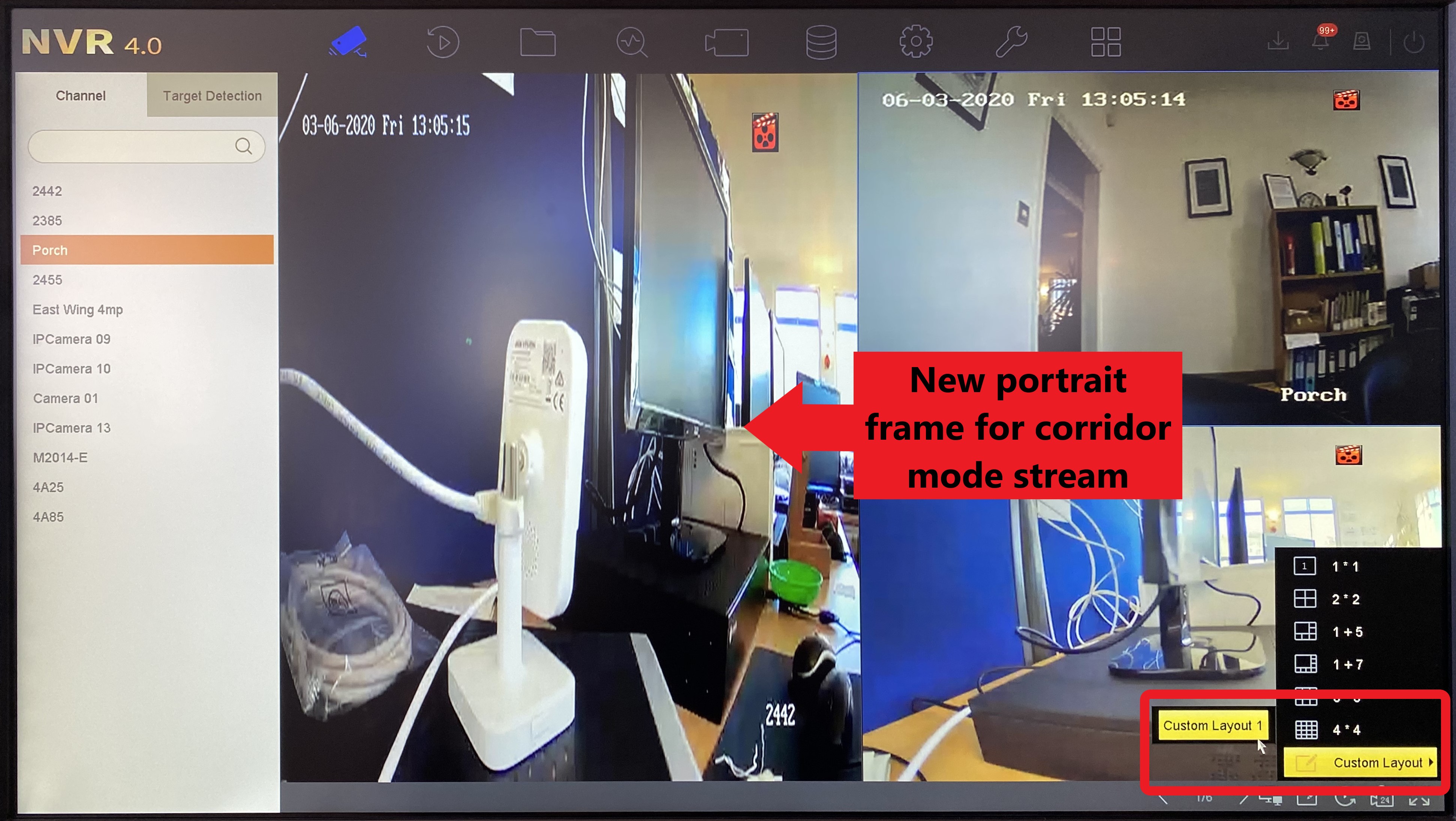
You should now be up and running with corridor mode set up properly on your camera! Feel free to start a new thread or comment below with any other questions or suggestions. Thanks for reading!
How Do You Setup Event Pre & Post Recording for a Hikvision Camera?
To Adjust the smart event pre-record and post-record you need to follow these steps:
1) Log in to the NVR/Camera
2) Go to Configuration > Storage > Schedule Setting > Record Schedule
3) Click the ‘Advanced’ button at the top right of the record schedule
.
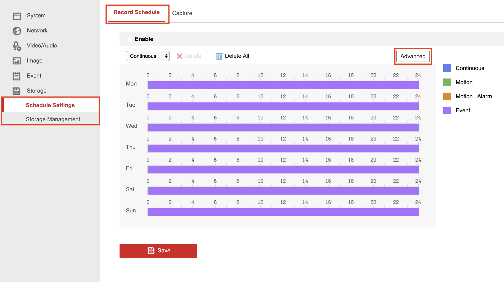
4) Select the duration you want from the pre/post record dropdowns and click OK
.
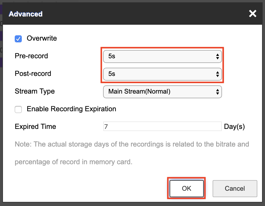
One thing to be aware of with event pre/post-recording is what Hikvision call a Buffer Zone. The buffer zone is simply a bracket of footage around the current moment in time that is continually recording/erasing, this buffer zone allows you to record only by event but still have access to footage before and after the trigger event without having continuous recording enabled.
The issue is that the buffer zone is limited to around 2-4MB of storage and so the higher your resolution and stream settings the larger the files sizes are and thus the maximum duration of the buffer you can use is limited.
So basically an 8MP camera will not be able to have as long pre/post recording durations as a lower-spec 4MP or 2MP model. (unless you reduce the resolution/stream settings of the 8MP camera)
We recommend that to get the longest duration possible from your pre/post recording you should set them to the not limited option to use the full 2-4MB buffer capacity.
(One other thing to be aware of, there is no advantage or disadvantage for pre/post recording when using an NVR. Although the NVR is managing the event recording, each channel on the NVR is still set to the same 2-4MB buffer, the same as the individual cameras. So you would not get more pre/post recording capacity with 1x 8MP than you would with 8 x 8MP cameras on an NVR.)
How do I stop my Hikvision NVR from beeping?
If a Hikvision NVR notices what it deems to be a critical error, or “exception”, it will make a constant beeping sound to draw your attention to this.
These exceptions can occur when:
.
• A hard drive has not been installed or properly formatted
• There is an error with the hard drive, it has been damaged, or the cameras are just not recording properly
• A hard drive has been filled and not set to overwrite
• There is an IP conflict, preventing the NVR from operating properly
• The NVR detects an illegal login
• The NVR loses its network connection
Of course, ignoring these exceptions are not recommended. However, you can disable the beeping while you address whatever the issue is by following the steps below.
.
.
Step 1:
Connect to your NVR in a web browser by using its IP address and logging in.

Step 2:
Check what the exception that is causing the beeping is in the NVR’s logs. To find these, go to:
Configuration → System → Maintenance → Log
Set the log search so that the “Major Type” is “Exception”, with the start and end time covering a period when the beeping has occurred.
For example, you can see that it is an IP address conflict causing it in this case.
Note – Camera disconnections will not cause the NVR to beep.

.
Step 3:
Go to:
Configuration → Event → Basic Event → Exception
Find the “exception type” identified in step 2 in the dropdown on this page.
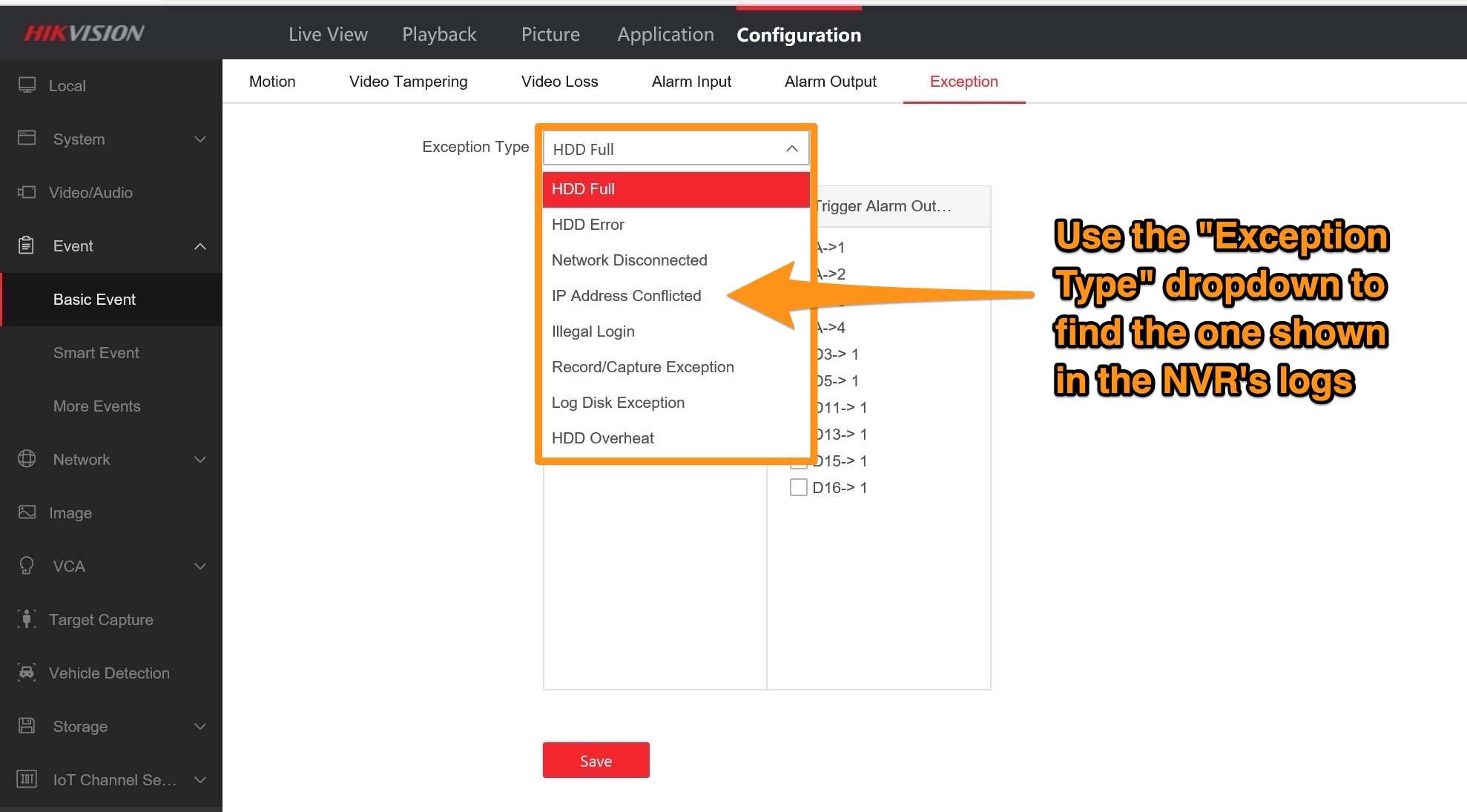
.
Step 4:
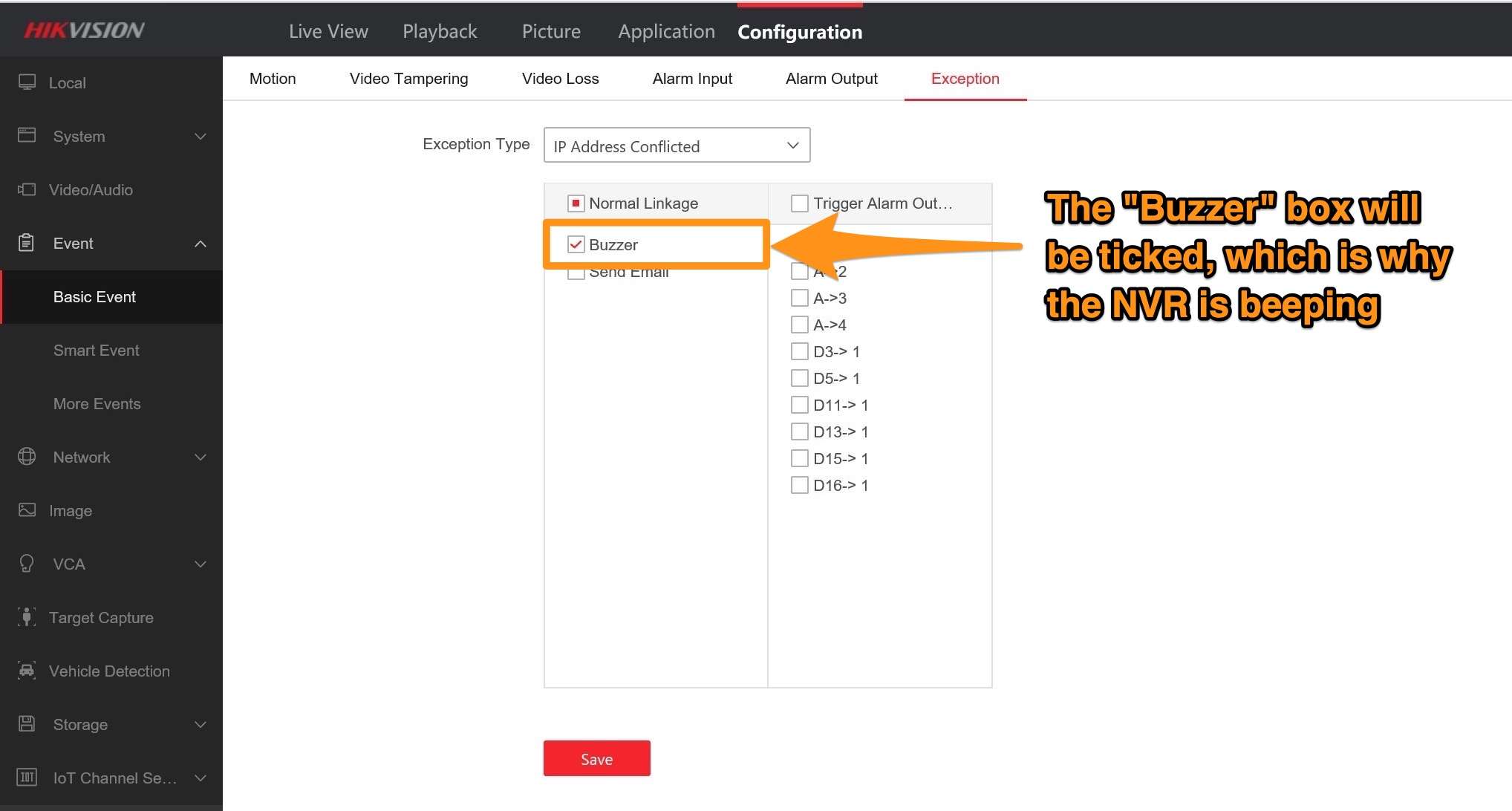
Select the exception shown in your logs from the dropdown.
You will see that “Buzzer” is ticked as a “Normal Linkage” action, which is what is causing the NVR to beep.
.
Step 5:
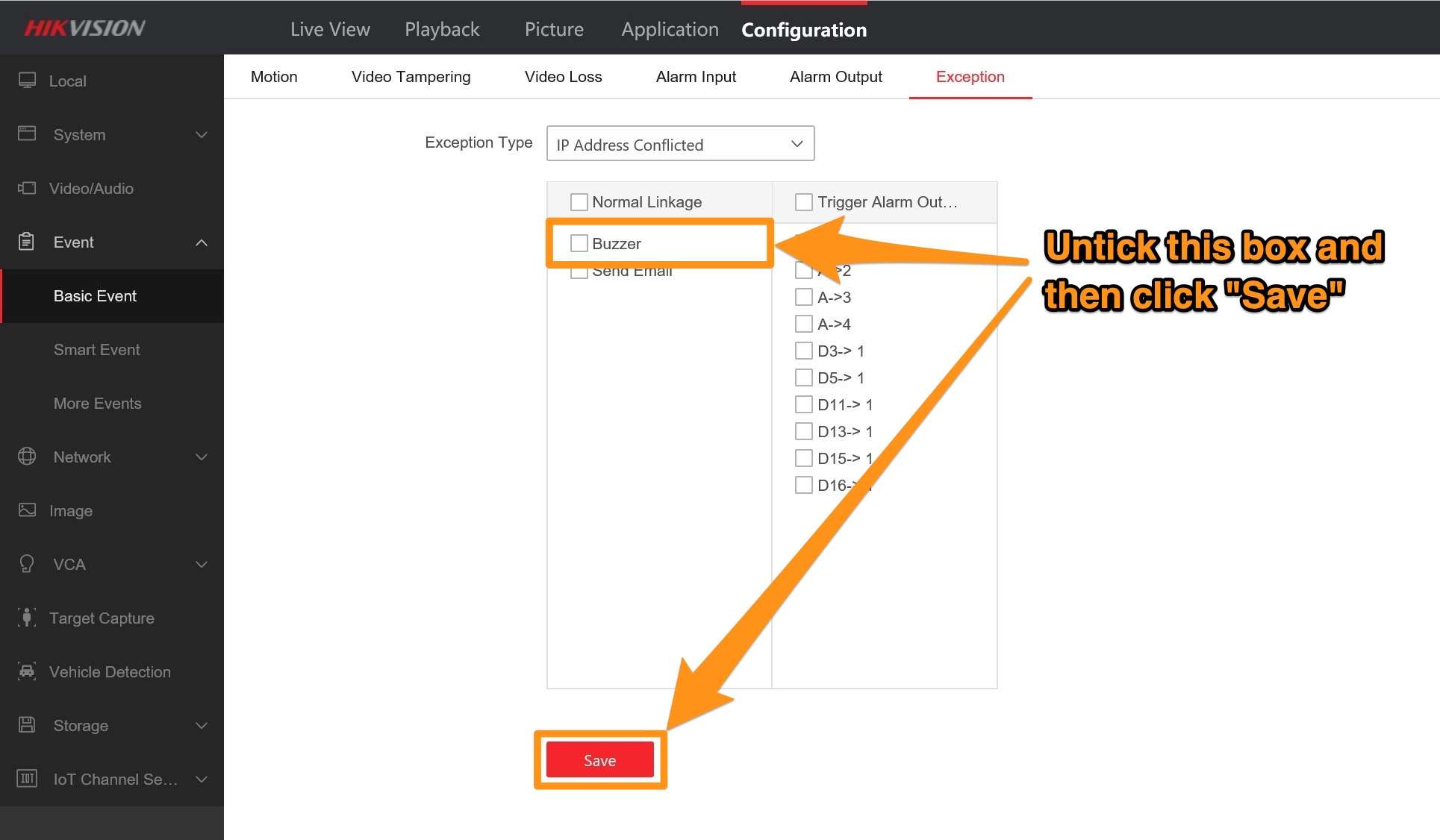
Untick this, click “Save”, and the beeping should stop.
My Hikvision NVR has both HDMI & VGA connections, can I connect two monitors to my NVR?
This question gets asked a lot and we have always assumed that as the larger Pro NVRs (9600 Series) have 2 x VGA & 2 x HDMI that they were the only models that would support any kind of multi-screen setup.
Today we did some tests with a selection of demo NVRs we have in our office to see if it was possible to connect two monitors to an NVR that only had 1 x VGA & 1 x HDMI, below are our findings from testing K-series & I-series NVRs
K-series (DS-7604NI-K1-4P(B) / DS-7608NI-K2-8P / DS-7616NI-K2-16P / DS-7716NI-K4-16P / DS-7732NI-K4-16P)
When we connected a monitor to both the VGA & HDMI of a 7604 4-channel NVR we were able to see the usual K-series GUI on both screens at the same time, but with the older K-series GUI when viewing on two monitors your actions will be synchronised (e.g. when you move the mouse on one screen the mouse will do the same movement on the 2nd screen, and this is the same for any action whether it’s opening menus and selecting individual live streams).
So the main disadvantage of this is that you can’t have different live views streaming on each monitor, both monitors will show exactly the same thing and the only difference will be that one will be a VGA quality. The advantage of these synchronised displays is if you have a setup with say a large wall-mounted monitor and a smaller desktop monitor,
you can have the HDMI output to the big screen while you operate from a smaller VGA screen, this kind of setup would be useful for any situation where you need to demonstrate a feature of the NVR or play back footage in real-time to a large group of people.
I-series (DS-7608NI-I2-8P / DS-7616NI-I2-16P / DS-7716NI-I4-16P /DS-7632NI-I4-16P / DS-7732NI-I4-16P)
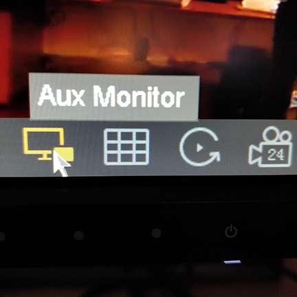
We have a 7716-I NVR as part of our demo system in the office and when we connected two monitors to the VGA & HDMI connections on the back we got the live streams displayed on both monitors just like we did with the K-series NVR. The difference with the I-series NVRs is that they use the latest 4.0 GUI, and on the live view page of this new interface you will find an icon in the bottom right
of the screen labelled ‘AUX Monitor’ (see image below), clicking this icon allows for you to switch control between the HDMI & VGA screens and allows you to move through the NVR menus on one screen whilst keeping the cameras streaming on the 2nd screen.
.
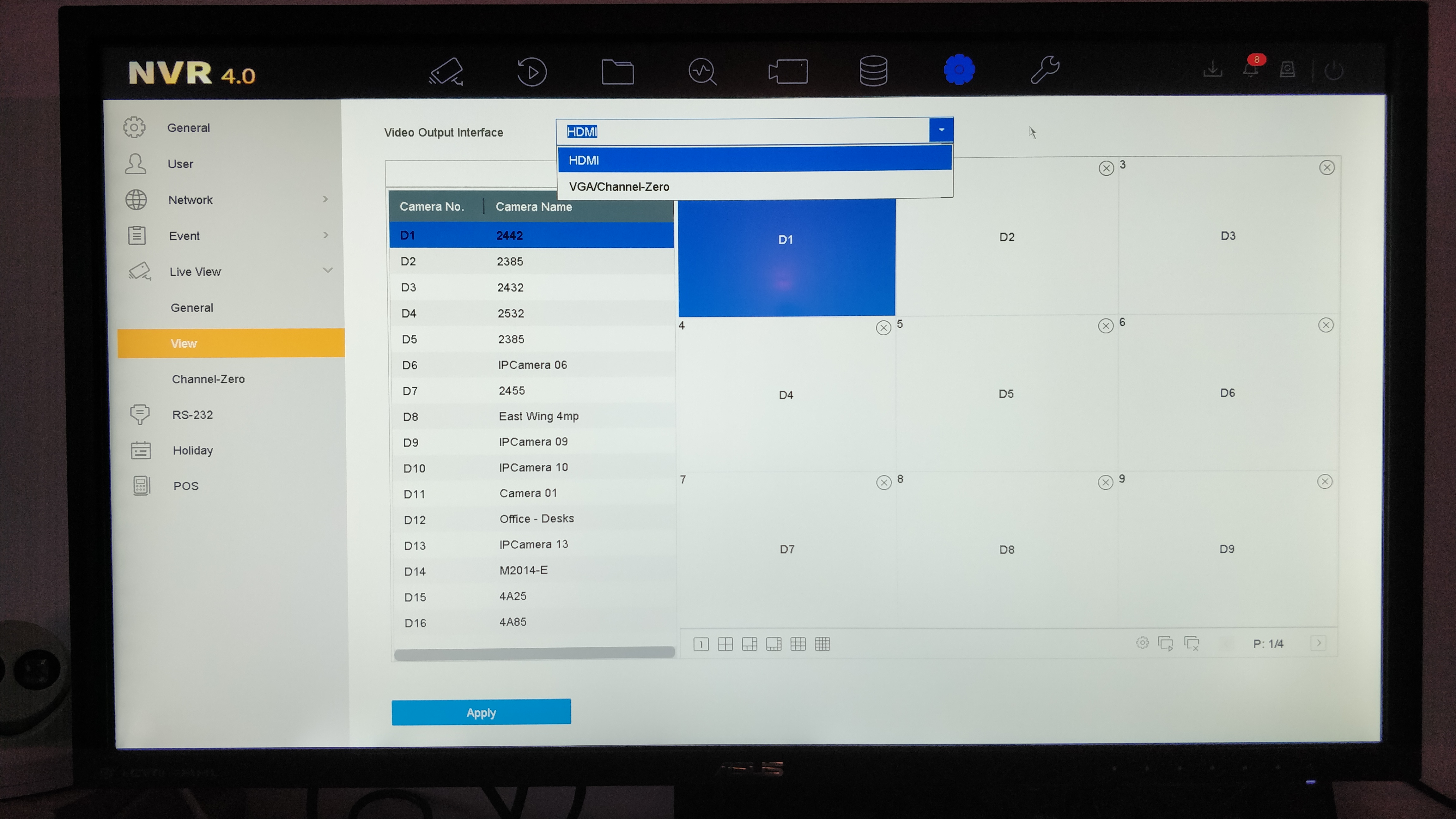
Now that you have the ability to switch between and control multiple screens you would obviously want to be able to set each screen up with their own camera stream layouts, to do this simply go to the System page (cog icon at the top of the 4.0 GUI) and then click the Live View tab and select the view page from the dropdown options. On this page you can switch between the HDMI & VGA screen and set the camera stream layout for each monitor (see image below).
There are limitations to how you can set the layouts, you can set the same camera to appear on both screens in the same place or in different positions and you can also spread all 16/32 cameras out across
the 2 screens, the main thing you can’t do is have a camera appear in different positions when using different live view layouts on the same screen (e.g. if you put camera 1 in the top left position for the 2*2 layout it will also appear in this top left position when you switch to the 3*3 layout).
.
9600 Series, Deep in mind, and Other NVR models
We don’t tend to get hands-on with these larger, top of the range NVRs but as you will see from the product pages and datasheets for these models a lot of them have 2 x VGA & 2 x HDMI connections. We assume that the 2 x connections on these models takes the multi-screen setup one step further by allowing you to seamlessly
move your mouse between screens (like you can with a 2 screen setup on a PC), thus allowing you to adjust each screens layout with ease and see all your camera streams in full quality via HDMI connection on both screens. (be aware that you will only see the full resolution stream of each camera when you select to view main-stream)
If anyone out there on the forum has had experience using two monitors with a 9600 Series NVR (or any other top of the range NVR with dual VGA/HDMI ports) then please share any information you have in this thread.
How do I set my Hikvision ColorVu camera’s built-in light to turn on during event periods?
We’re often asked if a ColorVu camera’s built-in supplementary white light can be programmed to turn on during VCA event trigger periods, such as during instances of motion detection, intrusion detection, or line crossing detection.
After testing, we can confirm that this is now possible on all 2nd Generation ColorVu cameras (any with a ‘G2’ in the part number) and works reliably.
In effect, it means the light on the camera can be used like a PIR floodlight, but with more control over a number of variables. Notably, trigger object type (human, vehicle, or both), the motion detection area, and direction of trigger object movement.
Please see the below steps for instructions on doing this.
.
.
.
Step 1:
Connect to your camera directly in a web browser, even if it is recording to an NVR.
If your camera is connected to your local network, just use its local IP address to do this.
If it is directly connected to your NVR’s PoE ports, then you will need to use the virtual host feature to connect to the camera via your NVR’s Camera Management page.
.
Step 2:
If you have a ColorVu camera from the G3 platform, then make sure you have installed the firmware, version 5.5.800 (build 210628), or later.
If you have one of the G5 models (indicated by a ‘C’ at the end of the part number), install version 5.7.2 (build 211228).
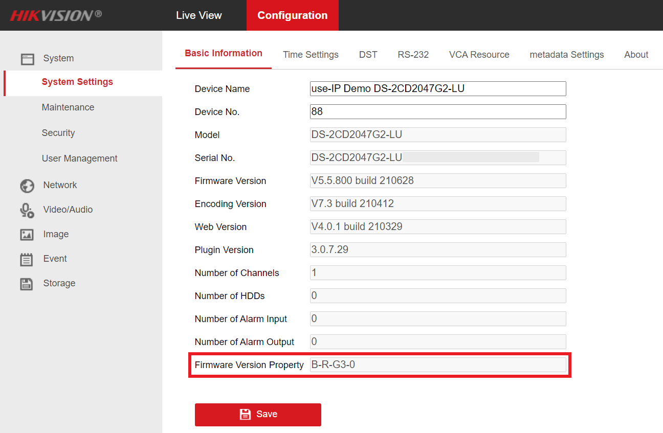
You can also check your camera’s platform when connected to it in a web browser by going to:
Configuration → System→ System Settings → Basic Information
The platform will then be indicated by either a “G3” or “G5” in the “Firmware Version Property” box:
Note – Please see this guide for instructions on how to check and update the firmware on your camera.
.
Step 3:
Once you’ve logged in, navigate to:
Configuration → Event → Basic Event (for motion detection) / Smart Event (all smart event options support this) → Select your preferred event type
.
Step 4:
Enable and set your event up in the Area Settings and Arming Schedule pages, this guide explains how to set up motion detection, line crossing, and intrusion detection.
.
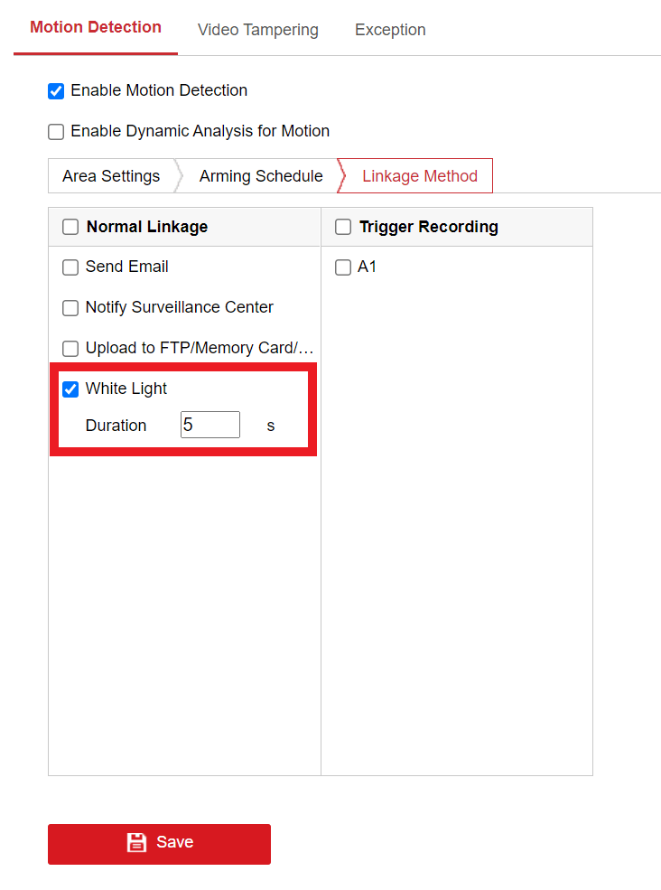
Step 5:
Navigate to the “Linkage Method” page, tick the “White Light” box, and set how long that you want it to remain on for on event triggers (in seconds) in the “Duration” box.
Click “Save” once this is done so the settings are kept.
How do I use a Hikvision NVR’s “Virtual Host” feature?
One of the most successful selling points of a Hikvision NVR to many small-setup customers is the “Plug and Play” functionality that simplifies the setup process of their surveillance system.
However, plugging a camera directly into a port on the NVR, unfortunately, does not allow you to access the camera via its own internal LAN IP using a browser due to it being on the NVRs internal network, and this can significantly reduce the number of configuration options you have access to.
The NVR does allow you to configure many options for each connected camera, but some essential features are only accessible via connecting to the camera itself (such as audio codec options). This was of course a big problem previously.
With the advent of newer firmware and models of NVR, Hikvision has introduced a feature called Virtual Host. Activating this feature turns your NVR into a “host” for the cameras allowing you to connect to them via a browser. Essentially, the NVR forwards all traffic received from your browser to the appropriate camera you’re trying to connect to, eliminating the biggest problem of plug and play functionality.
.
.
Step 1:
First of all, access your NVR via a web browser. If you do not know the LAN IP of your NVR, download Hikvision’s tool SADP tool, which scans your network for any Hikvision devices that are connected and allow you to see and change their network settings, including the IP address.
.
Step 2:
Once you’ve logged in, navigate to:
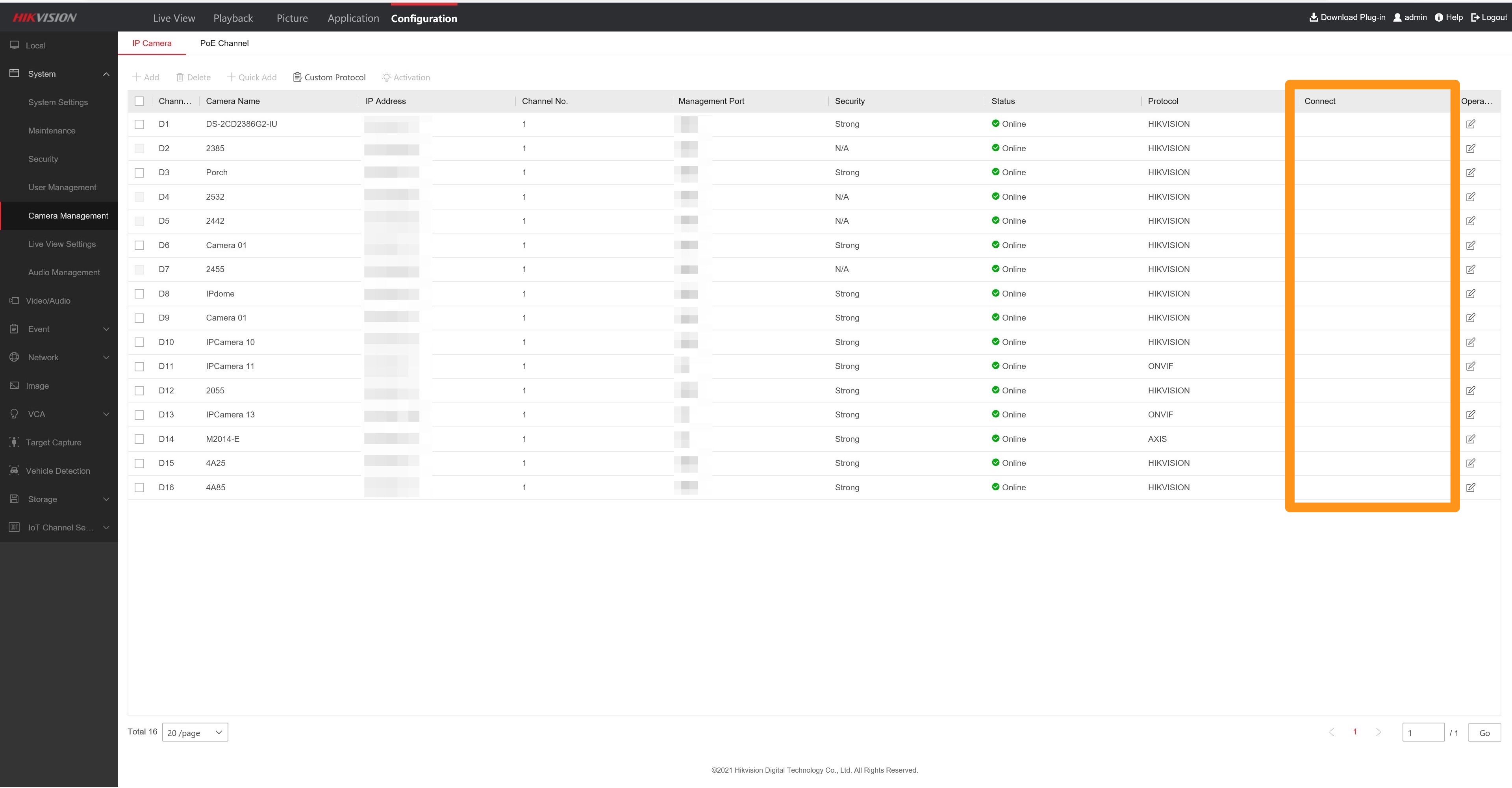
Configuration → System → Camera Management
.
.
This screen displays all the connected cameras on your NVR. Notice that the final column labelled “Connect” is currently empty. We’ll be coming back here in a moment.
.
Step 3:
Now, navigate to:
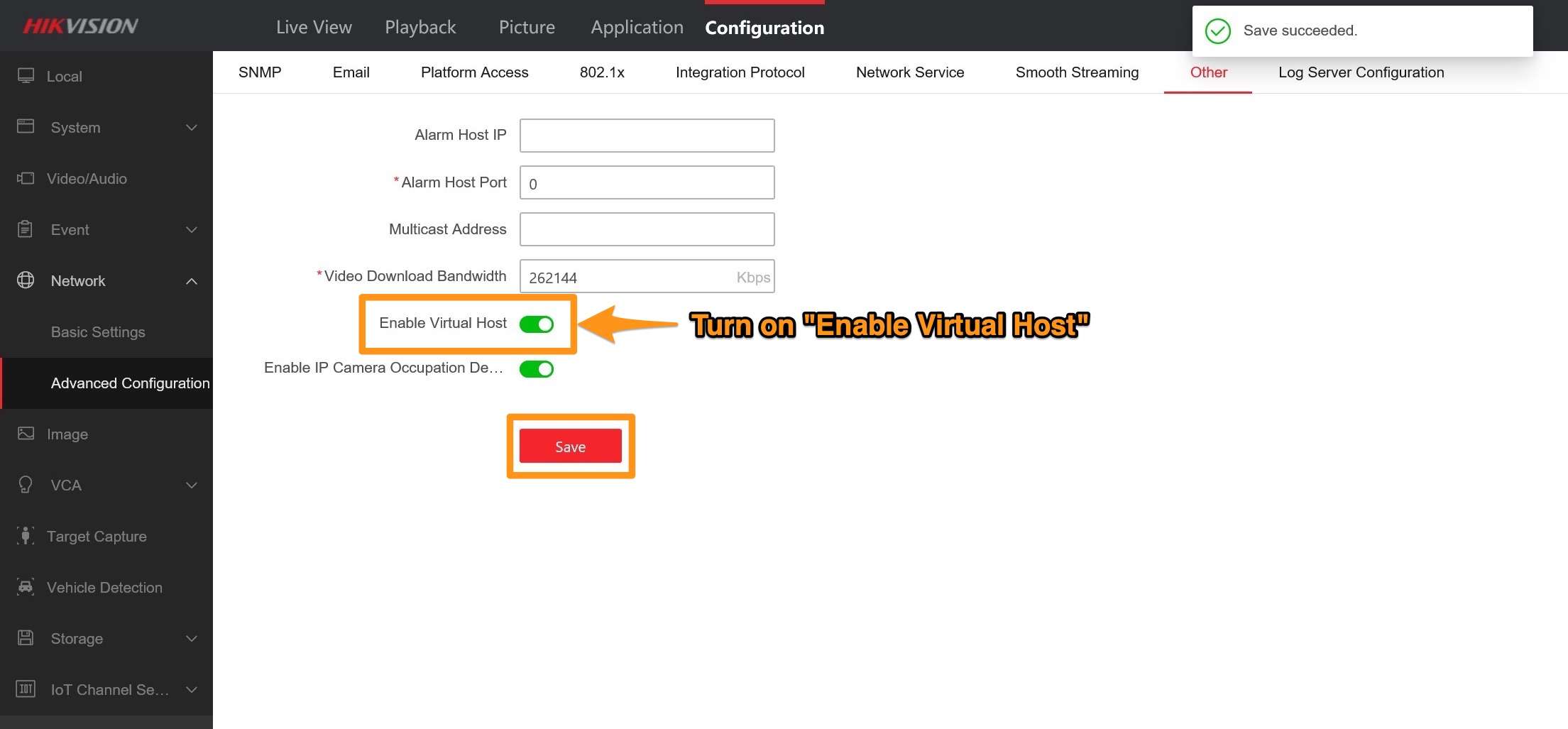
Network → Advanced Settings → Other
Turn on the Enable Virtual Host option.
Note – Your NVR will reboot when you click “Save”.
.
.
Step 4:
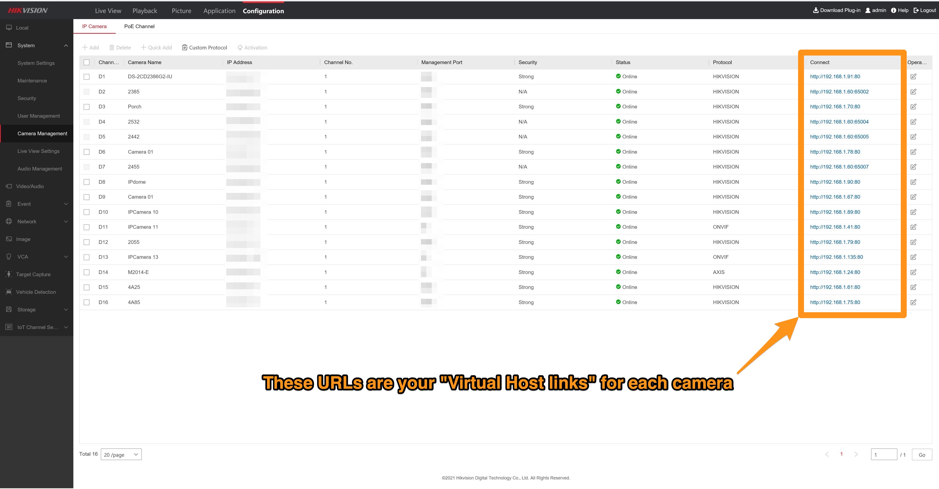
Now, navigate back to the Camera Management window from earlier. You’ll notice that the previously empty connect tab now features links for each camera currently connected to your NVR.
.
Step 5:
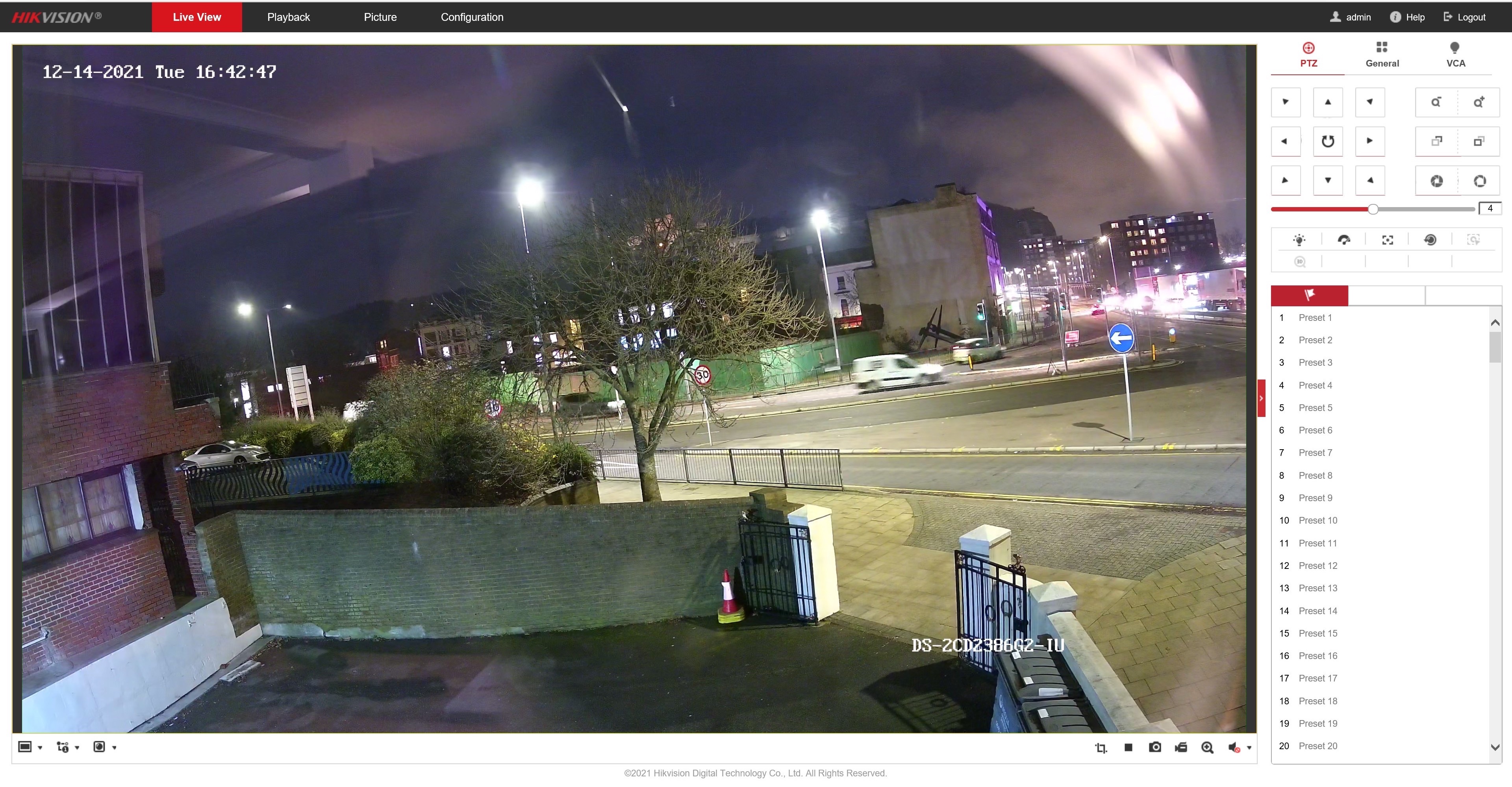
Click on any of these links to access the respective camera via your web browser:

That’s it, you’re done!
This should be useful when you want to access options on your camera that your NVR doesn’t feature. If you have any further questions feel free to ask, we’re happy to help.
Why am I not able to tilt my Hikvision PTZ camera upwards?
Hikvision PTZ cameras are not usually set by default to have their full range of movement enabled. This often means that cameras that are advertised as being able to tilt upwards are not able to do so straight out of the box, as this needs to be enabled in the camera’s settings.
You can check the movement range available on your camera in the PTZ section of its datasheet. Below is an example of this range shown for the DS-2DE5425IW-AE (S5):
.

0˚ tilt refers to the camera being in its home position, where it running parallel to the ground beneath and looking straight out at the scene.
Any negative figure (e.g. -15˚) here refers to the angle that it can tilt to upwards of the 0˚ position.
Any positive figure (e.g. 90˚) refers to how the angle of tilt available below this 0˚ position.
Cameras with “auto flip” will rotate 180˚ and then flip their image when it reaches its full 90˚ downwards tilt, which will give the illusion of you having a full 180˚ (or more) range when you try to continue to tilt beyond this 90˚ position.
To change the movement range currently set on the PTZ, you will need to connect to the camera directly in a web browser.
.
NB – If your camera is directly connected to an NVR’s network ports, then you will need to use the Virtual Host feature to access the camera’s backend. If it is connected to your local network, then you can just browse for its IP address to do this.
Then, go to:
.
Configuration > PTZ > Basic Settings > Max. Tilt Angle
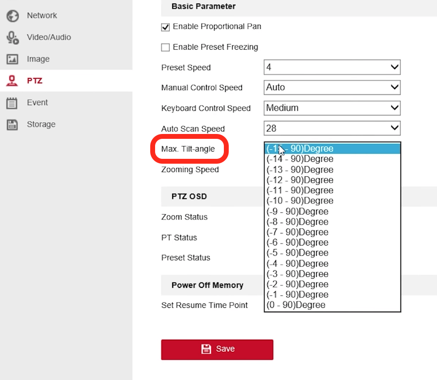
You should have some different options in this dropdown, depending on the maximum tilt range of your camera. If you want to enable the complete range of movement, then select the option with the largest range between the two figures (in this case, “-15 – 90˚”).
Once you have chosen an option that you’re happy with, make sure to click “save” at the bottom of the page so that these changes are updated on the camera.
How do you Shutdown a Hikvision NVR?
This is a common question by Hikvision users so we thought we would create a short forum post to give a clear answer on the possible ways to shutdown an NVR.
Direct Monitor Access
If you are accessing your NVR from an HDMI/VGA monitor then it is possible to shutdown the NVR from within the menus, depending on the NVR model the menus and shutdown process is slightly different as you will see from the below explanations:
I-series (76xxNI-I2 / 77xxNI-I4 / 96xxNI-I8 / 96xxNI-I16) & K-series (7604NI-K1/4P(B) / 76xxNI-K2 / 77xxNI-K4) NVRs – In the top right corner of the live view you will see a power icon which if you hover over will bring up text that says either ‘Power’ or ‘Power Off’, click the icon and a pop-up menu will appear with 3 options, one of which will be shutdown.
Click shutdown and a box will appear saying ‘shutting down…’ and then after 20-30 seconds, new text will appear asking you to switch the NVR off at the back to complete the shutdown.
(Above is for I-series and K-series NVRs that are running 4.0 GUI and EUI GUI respectively, if your NVRs are running older firmware and not using the latest user interface you will need to follow the below instructions)
7604NI-K1, E-series (76xxNI-E1 / 76xxNI-E2 / 77xxNI-E4), SE-series, and other older generation NVRs – Right-click the live view page and select the main menu from the dropdown, one of the menu options should be clearly labelled ‘Shutdown’ which when clicked should bring up the same 3 options as mentioned above.
Click ‘Shutdown’ and a window should appear with the text ‘shutting down…’ and roughly 20-30 seconds later new text will appear asking you to switch the NVR off at the back to complete the shutdown.
Browser Access
if you are accessing the NVR primarily from a browser then your only option for shutting the NVR down is to simply flick the switch on the back of the NVR because the browser menus do not include a button to shut the NVR down like you can with the direct monitor.
How do I know if the lens on my Hikvison mini dome is orientated correctly?
It’s easy to install your Hikvision mini dome only to turn it on and find that the image is upside down. If you’re not familiar with Hikvision cameras, adjusting the lens and settings can be confusing. This post will explain the two different ways that you can rotate your camera’s image by:
.
1.Manually rotating the lens itself.
2.Rotating the cameras image 180° in the image settings.
Part 1: How do I orientate my camera’s lens manually?
.
1.Remove the mini dome’s cover by loosening the screws surrounding the glass dome, shown in the image below:
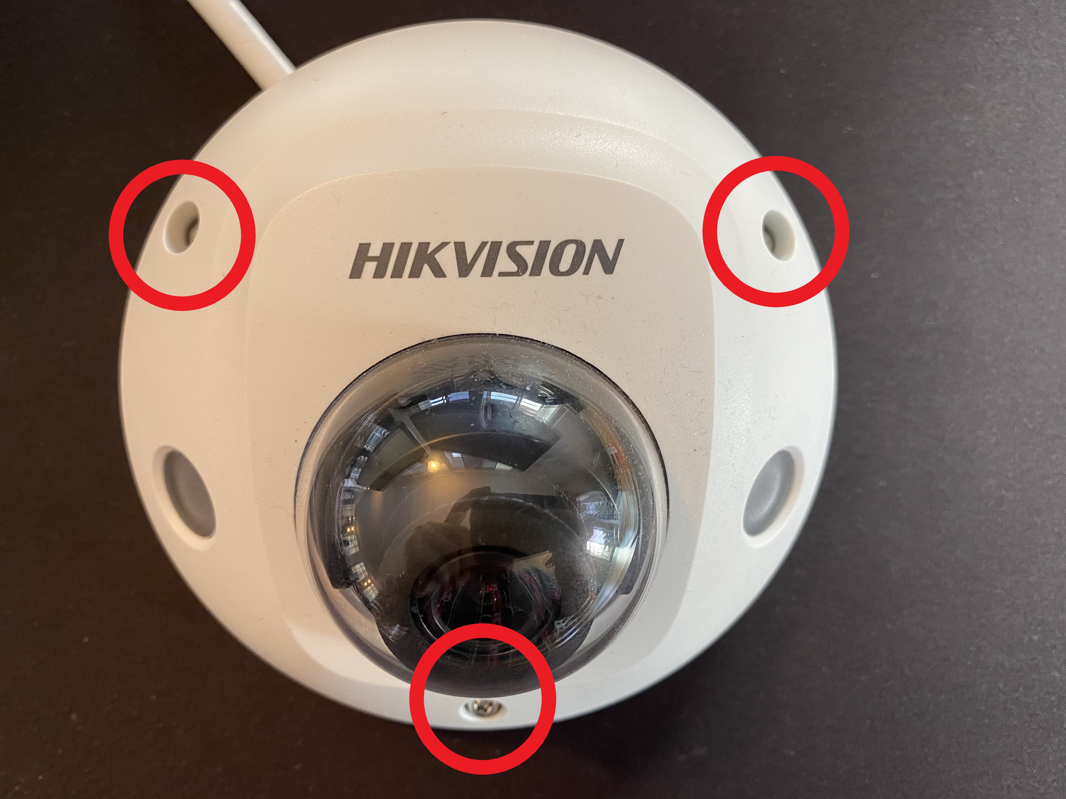
.
2.You should now be seeing something like the image below. Loosen the locking screw to the right of the lens, and then the lens bracket which locks the orientation of the lens in place. The lens is effectively attached to the camera body via a ball and socket joint, so this can be orientated however you like.
Part 2 of this guide explains rotating the lens in more detail, as well as how to rotate the lens on the turret and bullet styles of camera – How-to: How do I set up Corridor Mode on my Hikvision Turret, Bullet or Mini Dome IP CCTV camera?
NB – This image shows a camera with the lens rotated 180°, you’ll actually need this 90° marker to be in the 3 o’clock position, and the 180° marker pointing towards the bottom of the unit.
Hata! Dosya adı belirtilmemiş.
.
3.The lens should be positioned like the one shown in the below image. The small line marker located directly parallel to the 180° marker signifies the top of the lens. So, this needs to be pointing up, towards the top of your scene. This will orientate the camera’s view correctly. You should also make sure that the lens bracket is repositioned correctly so that the thicker part surrounds the top half of the lens.
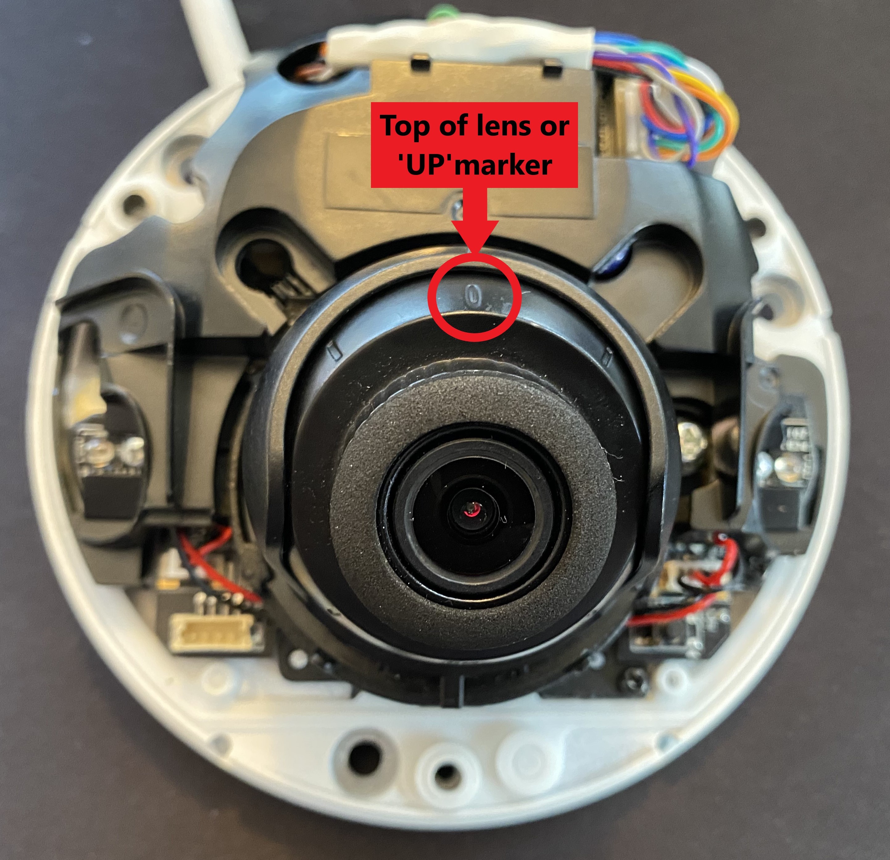
.
4.Now, tighten the locking screws and fasten the dome cover back in place, making sure the cover screws are tight to prevent water ingress into the camera. It’s always worth checking your camera stream before doing this to make sure that the camera view is orientated as you like.
For a guide on installing you Hikvision IP camera correctly to ensure it is properly waterproofed, please see this guide – Please Read: IMPORTANT – Installing Hikvision IP Cameras Correctly
Part 2: How do I orientate my Hikvision camera’s view through its settings?
.
1.Log into your camera’s web browser interface (not your NVR’s), by entering its IP address into the browser’s address bar. This will only work for cameras that are on the same LAN as your PC. If the camera is directly connected your NVR’s PoE ports, then you will need to use the NVR’s ‘VIrtual Host’ feature to access the camera’s own browser view, which gives you access to a wider range of settings.
NB – It is recommended that you use Internet Explorer if possible. If you are a macOS user, the best web browsers for this seem to be Google Chrome or Apple’s Safari. You might need to install Hikvison’s macOS Web Plugin as well.
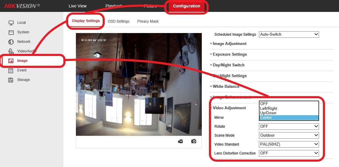
2.When you have access to the cameras in a web browser, go to:
Configuration > Image > DIsplay Settings > Video Adjustment
The different options are will adjust your image as described below:
Left/Right: The image will be flipped horizontally, so it appears as a typical mirrored image.
Up/Down: The image will be flipped vertically, which will still show a mirrored image of the default view as you are not actually ‘rotating’ the image 180°
Center: This will be the option that you need to select to rotate the image 180°, which will show the same view as physically rotating the lens would.
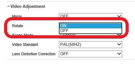
If you only need to rotate the image 90°, then setting the Rotate option to ON will do this, as shown below.
To rotate your view 270°, set the Mirror dropdown to Center, and then set Rotate to ON.
.
Thanks for reading – hopefully, this will prove helpful to some of you in the future! As always, please feel free to post any questions or feedback that you have below or by creating a new thread.
Hikvision Password Reset Options – 4 Ways the User can reset their Passwords
The new video from Hikvision (linked below) takes you through the 4 password reset options that the user can do themselves, these are:
1. Reset Password by reserved email
2. Reset Password via Hik-Connect App
3. Reset Password via Security Questions
4. Reset Password via GUID File
IMPORTANT: Not all of the above options will be available on all Hikvision products, also be aware that all the above options do require some level of pre-configuration to use them so if you have done none of the setups explained in the video you will have to follow the traditional reset file method as described here (remember though that we at use-IP will only reset passwords of our own customers)
How to Set up the Hikvision 2nd Generation Modular Intercom
We get asked a lot of questions by people looking to buy or who have already bought Hikvision’s 2nd Gen modular Intercom solution and for a long time, we have had to take the majority of those questions to Hikvision Support as we just don’t have enough hands-on experience with the intercom solution to answer them confidently.
Now we have finally found time to get a demo intercom system set up, test some of the features, and give you a guide of how to get a basic intercom solution up and running.
The below guide will initially** be split into 3 key sections with multiple sub-sections:
Single Module Setup (Video Intercom Module)
.
• Setting up the Video Intercom Module
• Setting up the Indoor Station
Three Module Setup (Video, Indicator, Keypad)
.
• Sub Modules & Dip Switches
• Setting Room Numbers & Unlock Codes
Six Module Setup (above + Display, RFID, nametag)
.
• Nametag & Display Modules
• Card Reader Module
The reason we have decided to cover it this way is that the modular nature of the solution means there are too many variations to cover specifically, so instead we will cover the details of the 3 most common setups and once you know the basics of all 3 any combination of modules should be achievable.
(**IMPORTANT – This will be a continual work-in-progress thread and we will add new posts with explanations of new features & settings as we test the intercom further and learn things from customers & Hikvision Support, this initial post will basically be a contents page for the entire thread)
Will the smart tracking feature on a Hikvision PTZ camera allow it to zoom in to its maximum zoom ratio automatically?
We’re frequently asked if Hikvision PTZ cameras will automatically zoom in to their maximum ratio when they are automatically tracking a target. After talking to Hikvision, we found out that you’ll need to do the following to enable the camera to do this:
On the camera’s menu (via a web browser) navigate to:
Configuration > PTZ > Smart Tracking
Here, set the Zoom Ratio to its maximum value, which will then allow the camera to automatically zoom to this maximum ratio.
Do It Youself – How To Silence a HikVision DS-7608NXI-I2/4S AcuSense NVR
Hi Guys,
I’m new to business here, but have made a video tutorial to decrease fan noise on my AcuSense 7608-NXI-i2-4S device. Maybe this helps others as internal construction of many NVRs from HikVision seems to be almost the same.
I also have some questions towards the community.
1. What is my latest firmware available for my NVR?
It is an AcuSense 7608NXI-i2-4s, but as I see it is not a full i-series device.
i-series are up to 4.22, but mine seems to be different. Can I use firmware here or not: Firmware – Latest HikVision Firmware for I-Series NVRs – V4.22.005
2. Scene change detection+alarm seems to be problematic. My cameras are AcuSense 2086G2 Bullet, but they do only detect scene change when going completely dark scene to normal recording scene. If I let them record a normal scene situation and then simulate a camera removal from wall situation – camera does not trigger a scene change event.
How to update the Hik-Connect App on your Android phone using Hikvision’s App Store
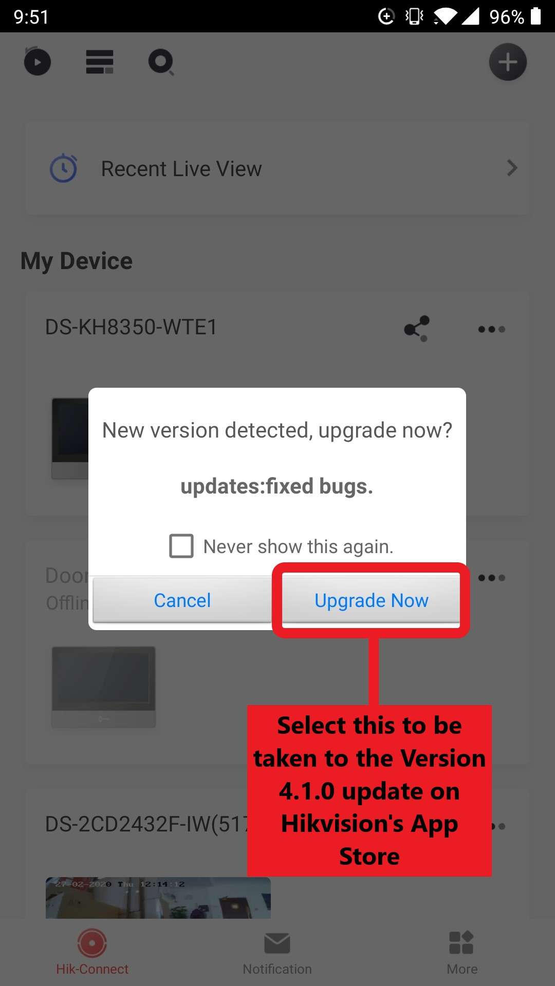
The method for updating the Hik-Connect App on Android devices has recently changed to mean that users can no longer update via Google’s Play Store. To use Version 4.1.0 of the app Android users now need to access Hikvision’s own App Store and update via the .apk file which is downloadable from there. The reasons for this change have been discussed in this post, as well as our thoughts on the situation.
This simple tutorial has been put together to walk you through this new method for updating in 5 easy steps, so that you can ensure you install the latest version of the Hik-Connect app is installed properly on your Android device.
Step 1:
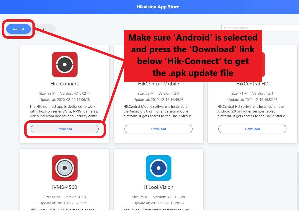
Open Hik-Connect if you have it already installed, and press the Upgrade Now button in the popup. If you don’t have the app installed or do not get this popup upon opening the act, this link to the Hikvision App Store will take you to the update file.
You need to make sure you open this page on the Android device that you wish to install the updated software on, as this will be the device that the update file is saved to! In the App store, make sure Android is selected in the top-left hand corner and then select Download beneath Hik-Connect to get the .apk update file.
.
Step 2:
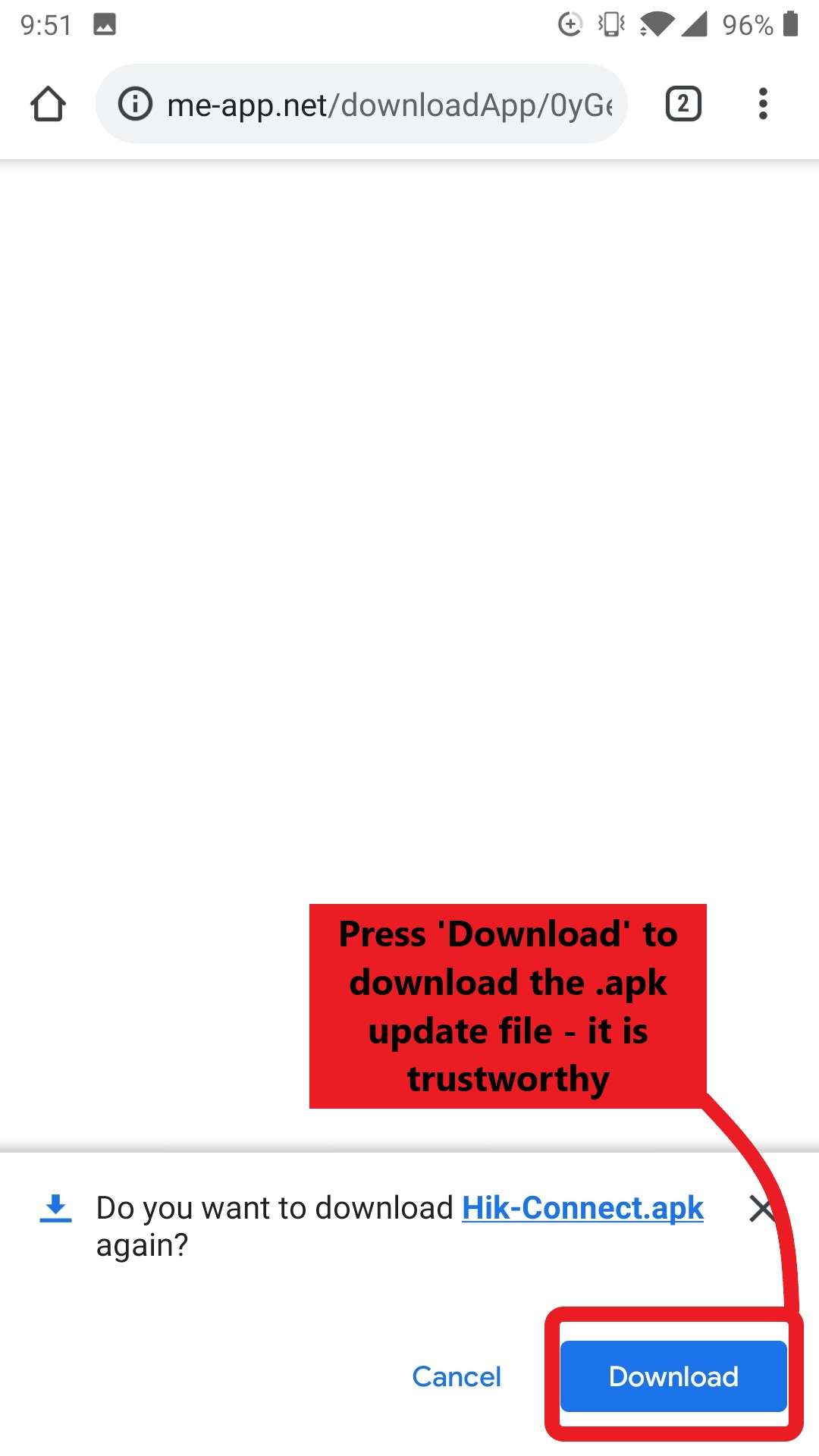
Press Download when the prompt to do so appears at the bottom of your screen. Don’t worry, this is a safe and secure link!
.
Step 3
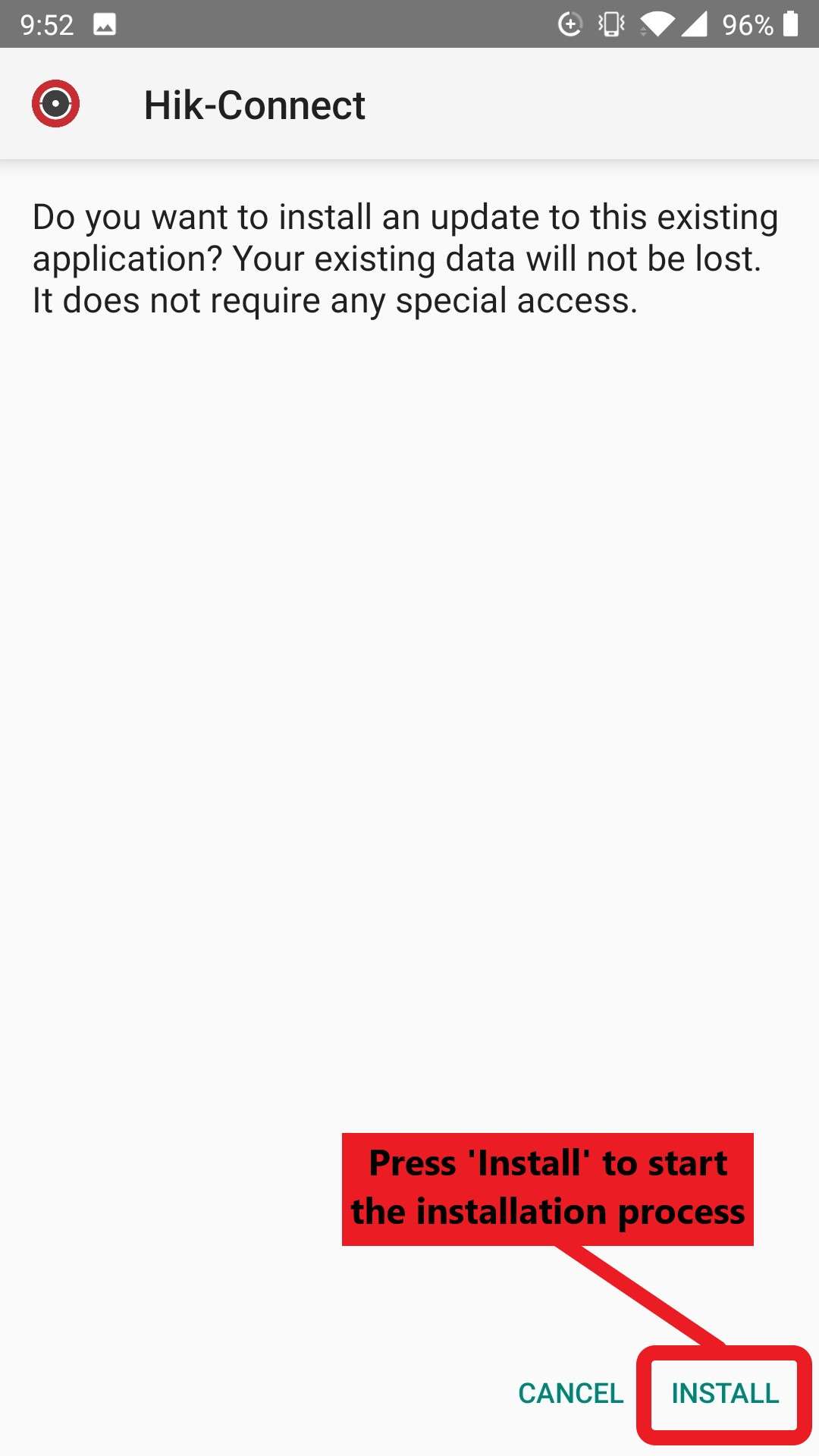
Select Install when the prompt to do so appears at the bottom of the screen.
.
Step 4
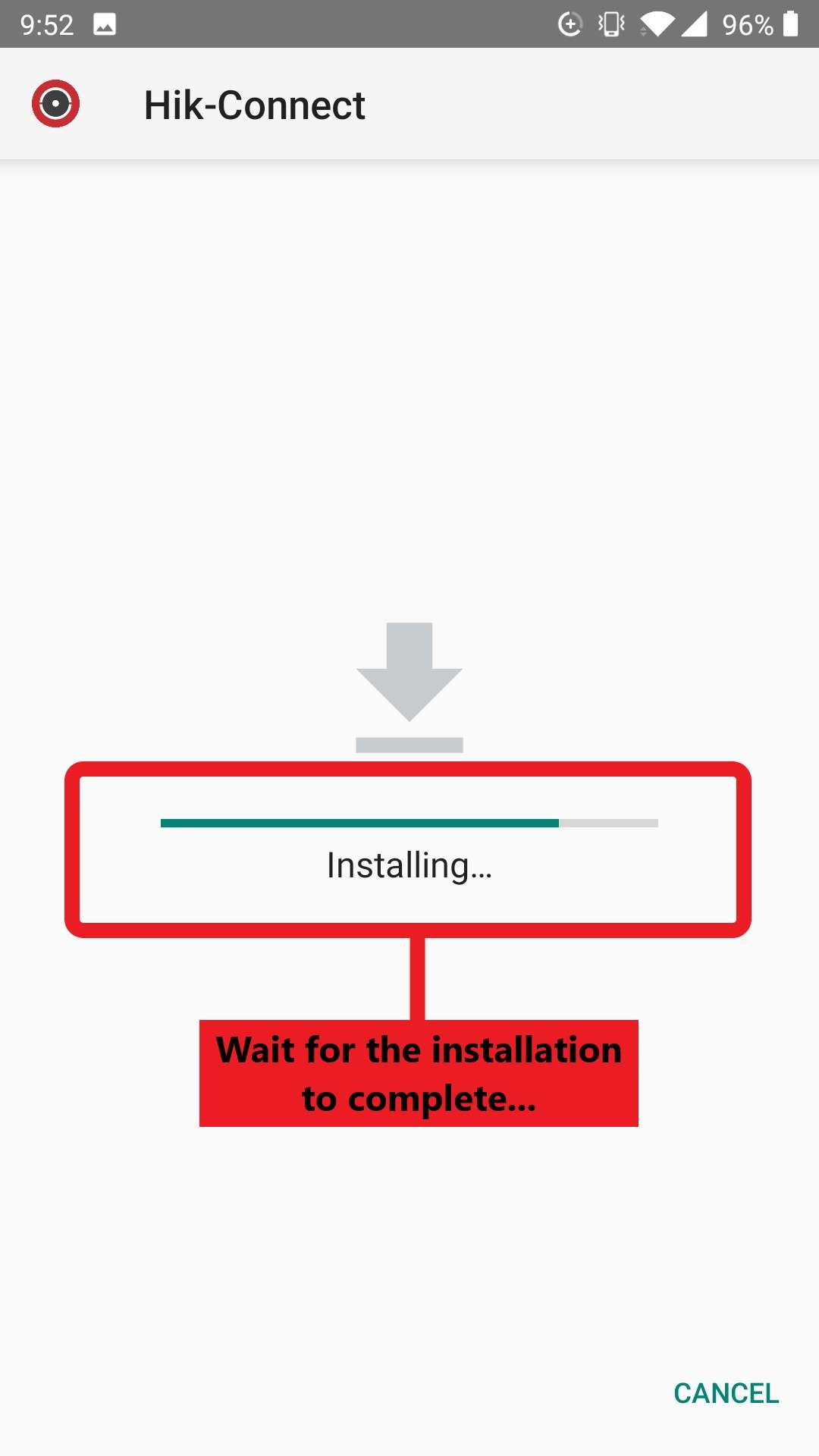
The installation will begin, wait for the progress bar to complete… Go and put the kettle on!
.
Step 5
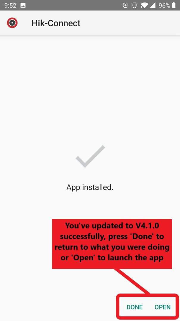
If you get the same screen as the one below, then you’re all done. You should now have the latest version (V4) of Hik-Connect installed on your device. You can either press Open to launch the app, or Done to return back to whatever you were previously doing. If your screen doesn’t say App installed with a tick above, then you’ll need to repeat steps 1-4 again!
.
How do I set up an alarm to work with an external device on my Hikvision NVR?
We often have customers ask us “how do I get my new NVR to work with an existing alarm system I already have installed” or “how do I connect something to the IN/OUT ports of my NVR?” Indeed, for such an important feature for the NVR’s to have, it is not the most straightforward to get set up with.
We thought it would therefore be useful to put together this guide to walk you through how to configure the alarm function, either through locally through your NVR and monitor, or through Hikvision’s iVMS-4200 software, in 10 easy minutes.
.
Contents:
Part 1: How to wire my alarm system into my NVR’s alarm input and output ports?
Part 2: How do I configure the alarm function settings of my NVR locally via a monitor?
Part 3: How do I configure the alarm function settings of my NVR remotely via iVMS-4200?
Part 1: How to wire my alarm system into my NVR’s alarm input and output ports?
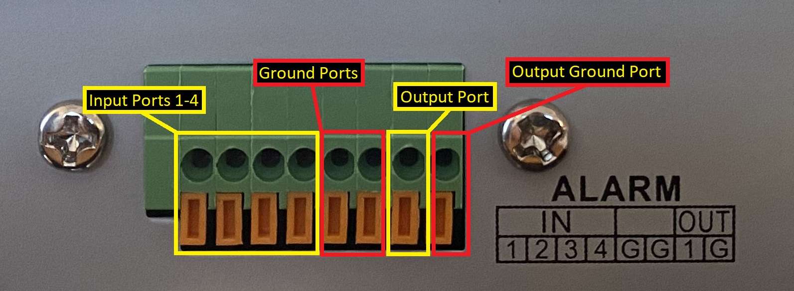
As daunting as it may seem when you look at the multiple different alarm ports in the back of your NVR, this part is simple enough once you know what you’re doing. If you’re struggling to find you alarm IN/OUT ports, they are the block of green connections which should be labeled as “ALARM IN/OUT” on the device.
The number of connections will vary here depending on the size of your NVR, the picture shown is of a smaller Hikvision DS-7608NI-K2-8P 8 Channel NVR. Larger NVRs will have more of each connection, but nonetheless, the process is the same.
Firstly, make sure you can locate the NVR’s “ALARM IN ” and “ALARM OUT ” ports, with their corresponding “Ground/G” ports. If you’re connecting a device to trigger your NVR cameras with an external event (e.g. a smoke alarm, PIR senor etc) then you’ll need to run the wires from the device into one of the input ports and its corresponding ground port.
If you’re connecting a device to be triggered by a smart event set up on your NVR (e.g. a siren or warning light), then connect the wires to the output port and corresponding ground port. All the ports are marked up in the picture below but should also be clearly labelled on your unit.
.
Part 2: How do I configure the alarm function settings of my NVR locally via a monitor?
Now that all the necessary connections are made, you’ll need to set up your NVR’s alarm function for it to alert the alarm system that you’re connecting to it.
Firstly, I’ll show you how to do this locally. You’ll need to boot up the NVR, once in the menu, navigate to:
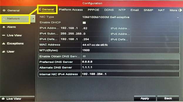
Menu > Configuration > Network > General
Here, you’ll need to insert your network’s IPv4 address, IPv4 subnet mask, IPv4 default gateway and your preferred DNS server:
.
• If you’re unsure of your IPv4 address, subnet mask or default gateway, our tutorials on How To find your router and PC’s IP address using a Windows PC or How To find your router and Mac’s IP address using a Mac show you how to do so. Please note, you need to make sure the PC you use to find these is hard wired via a network/Ethernet cable do make sure this turns up the correct addresses for your network/router.
• Unless you know of a preferred DNS server that you’ve set up yourself, Google’s public DNS server address (8.8.8.8) should work fine. It’s worth entering an alternate backup DNS too beside Alternate DNS Server, Cloudflare’s public DNS address is a good option (1.1.1.1). Follow this link for a list of the best publicly available DNS servers.
Now, navigate to:
Network > Email
At this screen, you’ll need to fill in all the fields as appropriate to your Email account. If you’re unsure of these, then complete the fields as below:
Enable Server Authentication: Tick/check this box
User Name: Insert your email address here
Password: Insert the password you use to access this email account
SMTP Server: If you don’t know this, follow this link for “finding your SMTP server address”
SMTP Port: Insert either 25 or 587 here
Enable SSL: Leave this box unticked
Sender: Insert the first part of your email address (everything before @)
Sender’s Address: Insert your email address here
Select Receivers: Insert “Receiver 1/any name” here
Receiver: Insert your email address (same as Sender’s Address)
Enable Attached Picture: Tick/check this this box, it will mean that you’ll receive picture of anything that triggers your cameras’ alarms in an email.
Interval: Insert 5s (5 seconds)
.
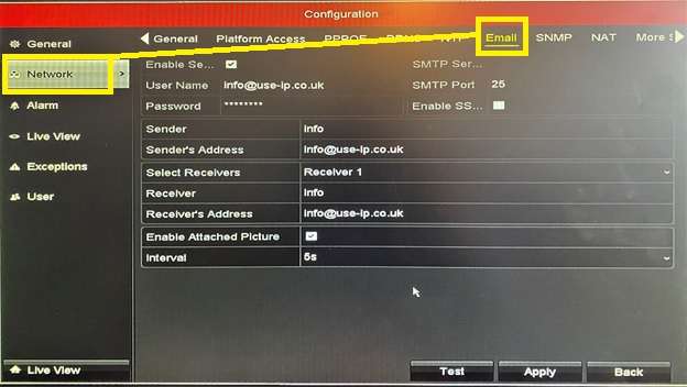
When you’ve completed these fields, navigate to:
Menu > Camera
Ensure all your cameras are properly connected to the NVR and are visible on this screen. If you haven’t yet added any cameras to your NVR, this guide on adding Hikvision cameras to an NVR walks you through how to do so.
.
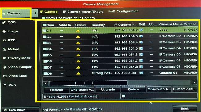
Now, navigate to:
Menu > Configuration > Alarm
This should take you to the Alarm Status menu. This menu lists the status all your alarm IN/OUT ports and any alarms that have been configured/assigned to these ports.
You’ll need to use this screen to check that you’ve set the correct Alarm Type for the alarm/device that you’re connecting. The options you have are N.O (Normally open) and N.C (Normally Closed). In brief, N.O alarm types use switches/sensors that normally remain open with no current flowing through them, so closing the switch allows for the flow of current and activates the alarm.
N.C alarm types, on the other hand, use switches/sensors the normally remain closed with current flowing through them, so opening the switch stops the flow of current and activates the alarm. There’s a lot to be said about N.O and N.C alarms but for now, you only need to know which category the alarm that you’re using falls under. If you want to take a journey down the N.O vs N.C rabbit-hole, I found this article on the differences between N.O vs N.C useful.
.
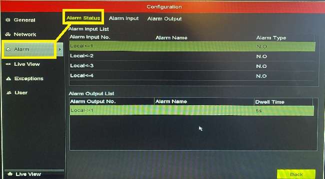
To assign an alarm to one of these IN/OUT ports, navigate to:
Alarm > Alarm Input > Settings (click on the small cog) > Trigger Channel
Choose the channel that you would like to trigger your alarm. In this case, we’ve selected channel 1.
.
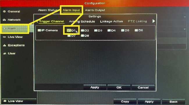
Now, navigate to:
Settings > Arming Schedule
Select the hours that you would like to schedule your alarm to be turned on for. Typically, this would be 24/7, so set the schedule for Monday, Week 1 as 00:00-24:00. Now, copy this schedule to the rest of the week by clicking Copy and then checking the box for All in the popup window. If you only want your alarm scheduled for certain days, then select the specified days in this popup from the list of 1-7 (1 = Monday, 2 = Tuesday etc).Once you’ve done this, click Apply.
.
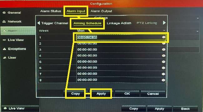
Finally, navigate to:
Settings > Linkage Action
Tick the boxes for Notify Surveillance Center and Send Email and then click Apply so that you email notifications whenever the alarm is triggered. If you have connected a separate device to be activated by the alarm in the NVR’s Alarm OUT port, then ticking the box for Trigger Alarm Output will activate this device when your alarm is triggered.
.
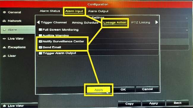
That’s it for the local setup section of this tutorial! Your NVR’s alarm function should now be set correctly.
Part 3: How do I configure the alarm function settings of my NVR remotely via iVMS-4200?
The first thing you’ll need to do is ensure you have the most up to date version IVMS-4200 installed and that you’re able to view the live feed of your camera(s) through the software.
If you haven’t already added your NVR to the program, navigate to:
Maintenance and Management > Device Management > Add
.
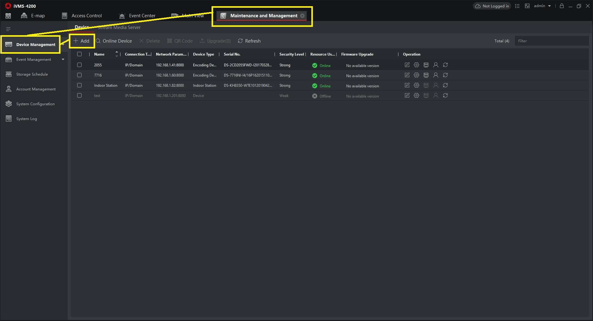
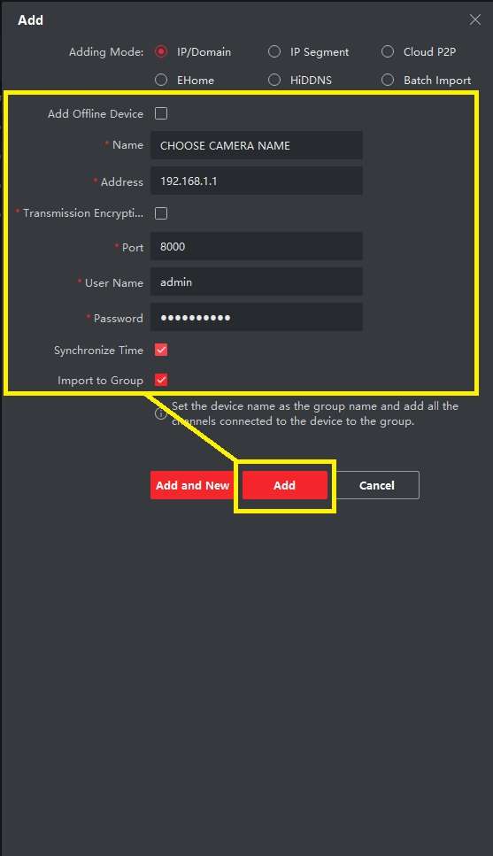
Add your NVR here by filling out the fields in the popup window, ensure the boxes beside Export To Group and Synchronise Time is checked and then click Add.
.
Now find the NVR on your device list and select:
Remote Configuration (the small cog listed beside your NVR) > [Basic Settings] > Event > Alarm
.
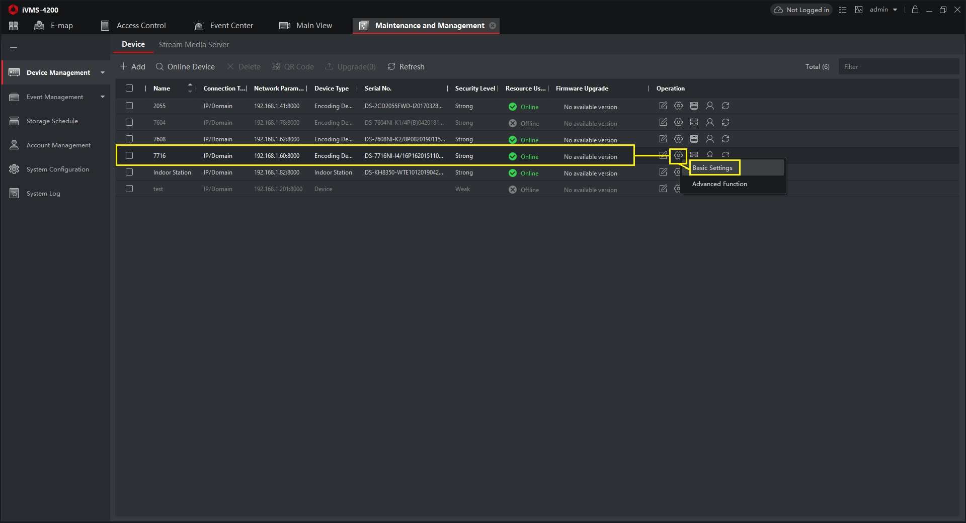
NB the configuration menu layout you will see henceforth will vary between two depending on the model of NVR that you have. I have included both variations for each step, so don’t worry if some of the below screenshots look unfamiliar.
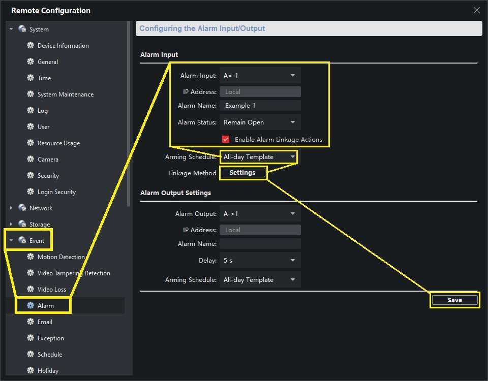
Fill out the alarm parameters here, e.g. as follows:
Alarm Input: Select your NVR’s channel that you would like to trigger your alarm (e.g.: A<-1)
IP Address: Local
Alarm Name: Name your alarm as desired
Alarm Status: Normal/Remain Open or Normal/Remain Closed depending on the type of alarm, see the first half of this tutorial to understand the differences
Enable Alarm Input Handling/Enable Alarm Linkage Actions: Check this box
Arming Schedule: All-day Template
.
.
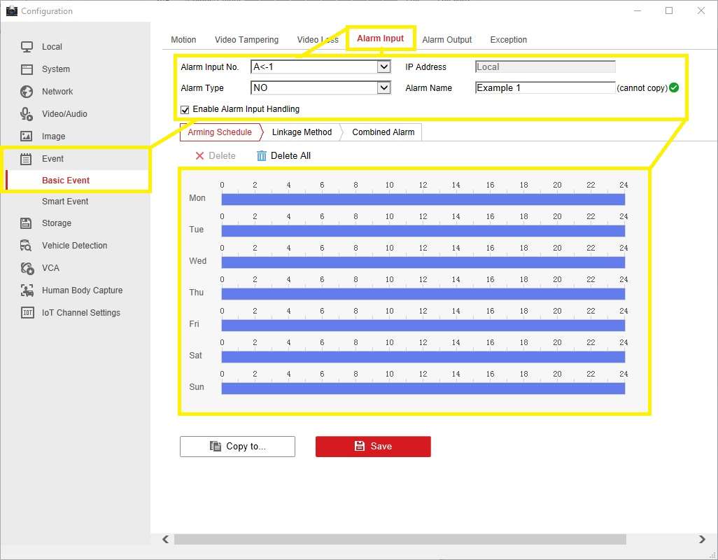
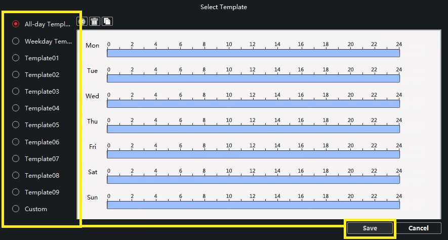
Open Arming Schedule, pick an arming template or a custom schedule of hours that you want your alarm active for.
.
Now, Click Settings beside Linkage Method. Check the boxes for Notify Surveillance Centre, Email linkage and Trigger Alarm Output (if you’re connecting an external alarm device to an output channel), then set the desired Triggered Camera.
.
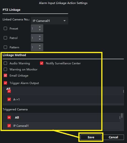
.
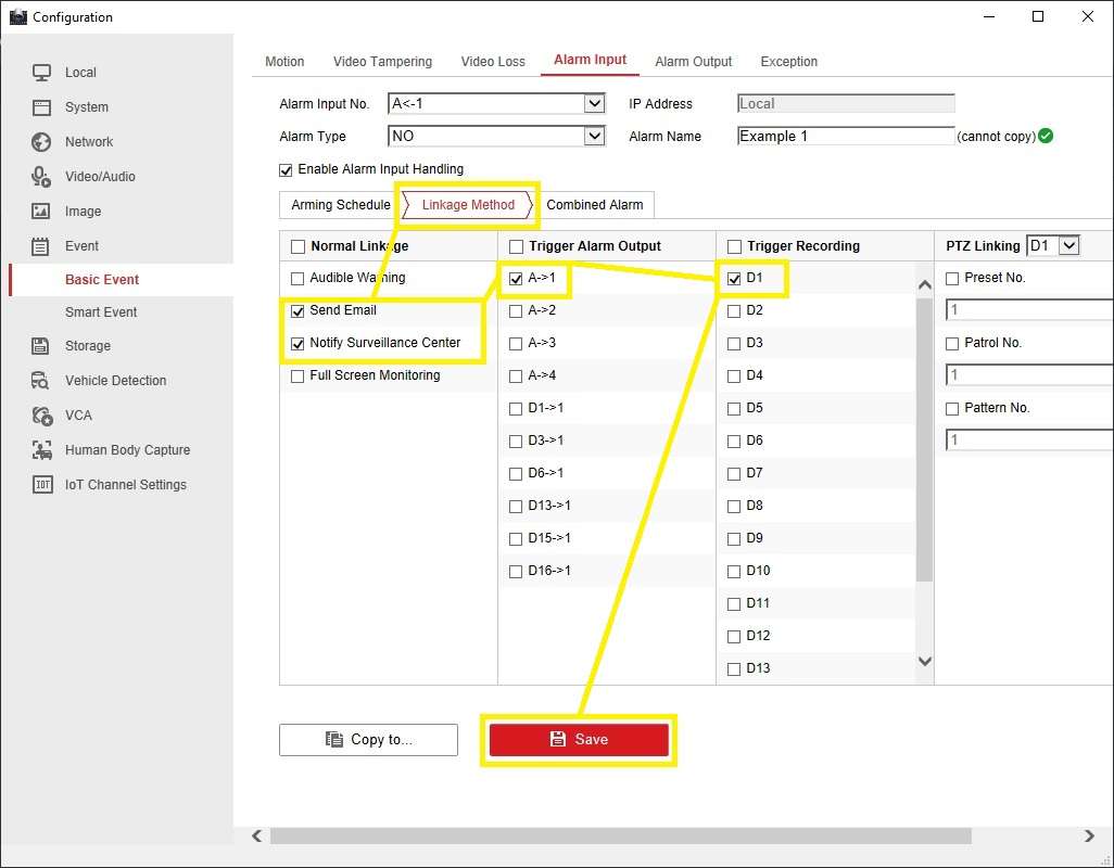
Click Save, and then Save again in the alarm configuration window.
Switch back to Main View and select your NVR from the side panel.
Now, click the small alarm picture and speaker icons at the very bottom toolbar so that they’re both enabled and look like the second image below. This will enable the alarm’s function to send an image of its trigger, as well as the audio.
.

That’s it for the remote setup! It’s always worthwhile testing your alarms to check everything is now working as it should be.
If you have any questions or comments to make, please do so in a separate thread mentioning this tutorial and I’ll get back to you as soon as I can.
How to Unbind a Hikvision Device using SADP on a PC
Unbinding a Hikvision device is not something that is required all that often, in most cases you can do the unbind from within the app. There are though some rare cases when the user does not have access to the Hik-connect account that the device is bound to, for example, if you have purchased a used device that has not been properly disconnected from its previous owners Hik-connect account or if you added the device to an employee’s account and they leave without removing the device from the app correctly.
As long as the Hikvision device has been set up correctly on your local network, then the process of unbinding should be pretty simple:
Step 1 – Open SADP on a PC
Step 2 – Click Refresh and select the device you want to unbind by ticking the box next to the device on the far left of the list
Step 3 – Click Unbind
Step 4 – Enter the current username and password of the device (this is NOT the username & password of the Hik-connect user you are trying to unbind the device from)
Step 5 – Enter the Verification Code and click confirm
You should then see a quick pop-up with a green tick saying Unbind Successful, If the device does NOT unbind and you get an error message like “The device is Offline” or “connecting device failed” then the most likely problem is that your DNS settings for the device are not set correctly.
You can change the DNS settings by logging in to the device using a browser and go to Configuration > Network > Basic Settings > TCP/IP and you will see the 2 DNS boxes at the bottom. We recommend that if you are unsure of what DNS to use that you enter default/most commonly used DNS servers which are shown below:
Prefered DNS – 8.8.8.8
Alternative DNS – 8.8.4.4
Once you have saved these DNS settings the unbind process should work
How do I update HikVision Firmware in just nine simple steps?
Updated 20-2-19 – corrected the link to the portal as Hikvision changed their url (again). Otherwise all is good. We use this method every day. Now viewed over 38,000 times.
Here’s how to upgrade your HikVision camera or NVR to the latest firmware version in just nine simple steps:
Step 1: Download the latest HikVision firmware to your PC.
Step 2: Extract the digicap.dav file (which is the actual firmware file) from the zipped file you downloaded.
Step 3: Copy that digicap.dav file to your PC’s root folder e.g. C://
Step 4: Browse to your NVR, camera, etc – using Internet Explorer:
Step 5: Login and navigate to Config -> Maintenance (screenshot attached below)
Step 6: Scroll to the bottom of the screen you’ll see Upgrade Firmware.
Step 7: Click the Browse button at the right-hand side.
Step 8: Browse to and select the digicap.dav file in your C:// drive
Step 9: Click ‘Upgrade’.
.
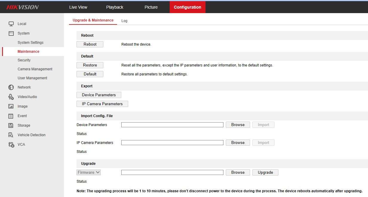
I have seen reports that you cannot leap updates, but not encountered the problem myself for some time (applies to old firmware of older models). If you do not succeed in upgrading from your current version to the latest version in a single step, please try interim releases.
Additional helpful tips:
.
1.Use a PC
2.Use a wired connection – PC and camera/NVR wired to your network
3.Use Internet Explorer browser (not Edge)
4.Move the digicap.dav file to your C:// folder (root of your HDD)
5.If you select/download firmware for the wrong camera family or device you will see an error message which states – “The type of upgrade file mismatches”
If you need any help finding the latest Hikvision firmware for your device:
Tutorial videos from HikVision Technical Support:
HikVision Firmware Update using Internet Explorer on your PC
HikVision Firmware Update using a monitor connected to your NVR
NVR Firmware update using a USB memory stick
Upgrade devices using IVMS-4200
NB We cannot guarantee outcomes – if you are one of our customers you will of course have our full support. We have only ever supplied official UK version HikVision cameras & NVRs. If you sourced your HikVision products from another supplier you may want to check their recommendations.
How To Set Up Live View & Playback Audio on Hikvision Cameras
There is a small selection of Hikvision cameras that support some sort of audio – audio I/O, built-in mic, 2-way audio – but on multiple occasions, customers have come back to us saying they are getting no audio on live view or playback. So to avoid this problem in the future we are creating this post to take you through the steps that must be completed to get audio from a Hikvision camera.
Step 1 – Update Firmware
Keeping firmware up to date is always important so it is always where we start with any issue, now most firmware should support the audio but if you’ve had a model for several years and never updated it you are likely on an old firmware and so updating just removes any potential problem that might be caused by out of date firmware.
EU Firmware Portal
UK Firmware Portal
The most common audio cameras will be EasyIP 2.0+ (2xx3G0) and EasyIP 3.0 (2xx5FWD/2xx5G1) which all use the same G1 Firmware.
Step 2 – Video & Audio
Login to the camera, go to the Configuration page and open the Video/Audio menu where you will see all the video settings. The important one for audio is the Video Type which needs to be changed from Video Stream to Video & Audio as shown below:
.
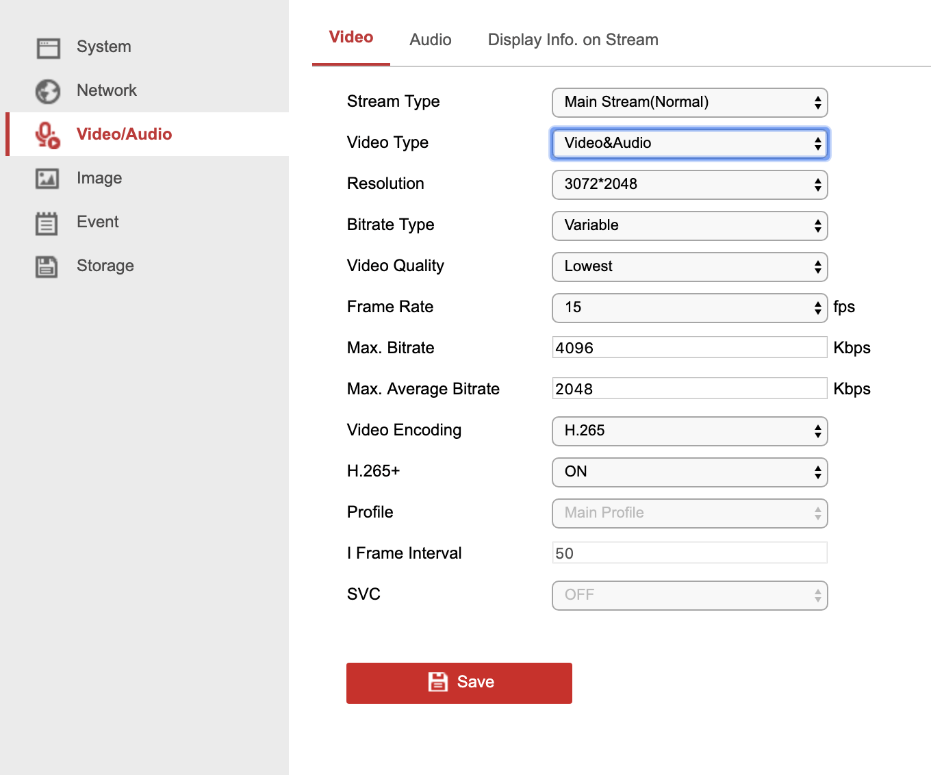
Make sure you also switch the Video Type of any other streams you are using, the main one for most cameras will be the sub-stream which is used when viewing the camera from the Hik-connect app. Also, if your camera is connected to a Hikvision NVR make sure to check the camera is set to Video & Audio in the NVRs Video Settings.
Step 3 – Audio
The final Settings to check are the Audio settings which more often than not out of the box is set up correctly and should look like the below screenshot:
.
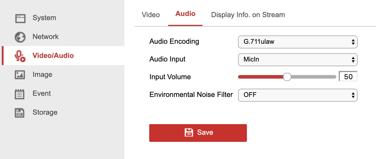
The only setting that might change depending on the model you have is the Audio Input option. If you have a camera with only a built-in mic or 2-way audio then the only option you will have is MicIn, but if the camera only has audio I/O connectors or has both options then you will have both MicIn and LineIn input options. Make sure if your camera has both options that you select the correct input for your setup, LineIn will be used if you have a more powerful audio device connected like an amplifier or a stereo microphone, while MicIn will be for smaller standard Mono microphones.
With all 3 of these steps completed, you should now have live audio from the camera on the browser, app, and direct monitor live view, but there is one final step to have your camera record audio.
Step 4 – Record Audio
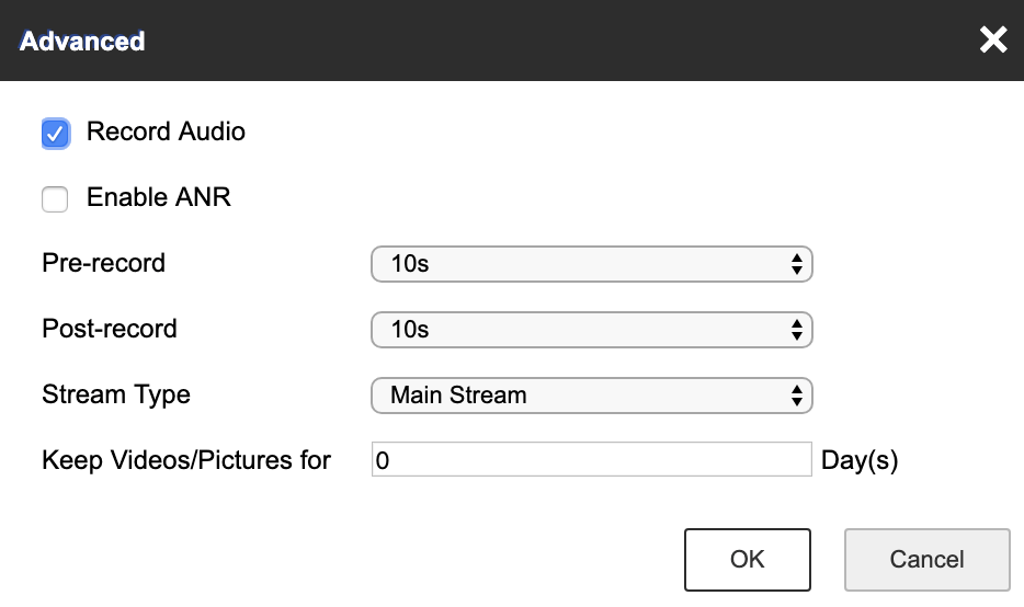
Login to your camera/NVR and go to Configuration > Storage > Schedule Settings and select the camera with audio, once you have the schedule for that camera onscreen you will need to click the Advanced button which you will see in the top right of the schedule. A pop up will appear and you will see an option to Record Audio, tick this option and click OK to apply the setting, now all the recorded footage from that camera will have audio.
.
.
.
