Verkada intercoms setup guide v1

Verkada intercoms setup guide v1, Verkada’s intercom solution enables you to answer calls, grant entry, and secure entrances from anywhere.

Get Started with Verkada Intercom Set up and connect your Verkada intercoms Updated over a week ago

Required. You need Org Admin and/or Site Admin permissions for your Verkada Command organization to complete these actions.

Table of Contents

What you need

• PoE-enabled switch or PoE injector
• DHCP-enabled network
• Cat5 or Cat6 cabling

Create a site

Sites are the logical way of grouping and managing devices within your Command organization. Site-level permissions make managing and viewing your devices easier. See Manage Your Sites and Subsites for more information on site creation and management.

Add an intercom

At least one intercom needs to be added to Command before you can see the Intercom tab in the All Products menu. Intercoms can be added to Command from the Devices page. See Add an Intercom to Your Site for more information.

Connect a door

You can pair an existing access-controlled door or wire a door to the intercom that can be unlocked by an intercom receiver. See Configure a TD52 and Wire a TD52 Video Intercom for more information.

Configure receivers

Receivers allow you to answer calls from an intercom and unlock any associated doors. See Add and Configure Receivers in Intercom for more information.

Licensing

Every intercom you manage in Command will need a license. Verkada licensing is applied for each Command organization, and the licenses co-term to a single expiration date. Your licenses may have been automatically added if you claimed your devices via order number. Otherwise, manually add the licenses from the Admin page. See Manage Your Licenses for more information on adding and managing licenses.

Connect your intercom

Recommendation. While Verkada intercoms are considered low-voltage devices that do not require a certified electrician to install, we strongly recommend you work with a system integrator or other professional for installation.

Please refer to the intercom setup guide for instructions on mounting and wiring the door port.

Power and network

Verkada intercoms use Power over Ethernet (PoE) for power and communication over the LAN. In most cases, intercoms will connect directly to an 802.3af PoE standard switch. PoE injectors can be used when a PoE switch is not available. See the intercom’s datasheet for more information.

Check network settings

Verkada intercoms are designed to be plug-and-play. However, if your environment includes a firewall with custom rules and policies, you may need to make some configuration changes to get your access controllers connected to the cloud. See Intercom Network Settings for more information.

Roles and Permissions for Intercom

Roles and Permissions for Intercom

Learn more about Verkada Intercom roles and permissions

Updated over a week ago

This article describes the set of roles and associated permissions for Verkada Intercom.

• Permissions are set using roles, which define the level of access users and groups have to devices and settings within an organization and its sites/subsites.
• User permissions specify what tasks users can perform and what features users can access in Command.
• Site-level permissions define what access a particular user or group has to the cameras within the site. Site-level permissions are configured using roles.

See Roles and Permissions for Command users for an in-depth explanation of the features and configurations available for overall Verkada Command usage and administration.

Verkada intercoms setup guide v1

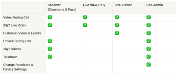
Verkada Intercom permissions determine who can receive calls, view intercom video, and unlock intercom doors. Intercom permissions depend on your site-level permissions, and whether you’re configured as a Receiver.

At a high level, these are the permissions granted to each level of Intercom devices:

screenshot2023 10 31at8 02 52am 605w255h

Site-level roles

Receiver

Required. You must be configured as a receiver to receive calls.

If you’re a Verkada Intercom Receiver, you have the baseline receiver permissions (as shown above). These baseline Receiver permissions combine with site-level permissions to determine overall intercom permissions within a certain site.

For example, if you’re a Receiver for a particular intercom, and a Site Viewer, you get all the Receiver permissions, in addition to the ability to view historical video and events.

Note: Receivers, such as Desk Stations and Session Initiation Protocol (SIP) phones are not tied to a Verkada Command user. This means that the user can only get Receiver permissions, regardless of the user’s site-level permissions.

Regardless of their site-level permissions, a Receiver can:

• Receive calls with video.
• See 24/7 live intercom video, even if not on an active call.
• Unlock the door both during and outside of a call.
• Talk down to the intercom.

Live-View Only

• Receive calls with video.
• See 24/7 live intercom video, even if not on an active call.

Site Viewer

• Receive calls with video.
• See 24/7 live intercom video, even if not on an active call.
• View historical video and events.

Site Admin

• Receive calls with video.
• See 24/7 live intercom video, even if not on an active call.
• View historical video and events.
• Unlock the door both during and outside of a call.
• Unlock the door 24/7.
• Talk down to the intercom.
• Change Receivers and device settings.

.

Verify a user’s eligibility to receive Verkada Pass calls

• A user who has previously logged in to Verkada Pass has a black and white symbol next to their name in the call list. To verify, hover over the Verkada Pass symbol. The tooltip should show Pass App (as shown).

7743538 verkadapass1

• A user who is configured as a Receiver and has never logged in to the Verkada Pass App should show Send Pass App Invite, which you can click to send an invite to that user.

7628594 verkadapass2

.

Set Org Admin permissions

1.In Verkada Command, go to All Products > Admin.
2.Under Org Settings, scroll down to and select Users.
3.Select the user who you want to grant Org Admin permissions.
4.Click the User Actions dropdown and select Grant Org Admin.
5.When prompted to confirm, click Confirm.​

Revoke Org Admin permissions

1.In Verkada Command, go to All Products > Admin.
2.Under Org Settings, scroll down to and select Users.
3.Click the User Actions dropdown and select Revoke Org Admin.
4.When prompted to confirm, click Confirm.

.

Set site and subsite permissions

You can set site and subsite permissions by adding a user, a group, or by existing users and groups.

Add a user

1.In Verkada Command, go to All Products > Admin.
2.Under Org Settings, scroll down to and select Users.
3.At the top right, click Add User.
4.On Add User:
1.Enter the user’s first name, last name, and email address.
2.(Optional) Check the Grant Organization Admin box to give Org Admin permissions.
3.Click Assign Groups to add them to one or more existing groups,
4.Click Add.
5.Under Site Roles, click Manage Roles and grant the user the desired role for each site and subsite.

Add a group

1.In Verkada Command, go to All Products > Admin.
2.Under Org Settings, scroll down to and select Groups.
3.At the top right, click Create Group.
4.On Create Group, enter the group’s name, and click Create.
5.On Add Members to this Group, check the box next to the members you want to add to the group and click Add.
6.On the new group page, at the top, click Site Roles > Assign Roles.
7.On Assign Roles:
1.Under the Role column, select the permission level you want to assign for each site and subsite.
2.Click Save.

Existing users and groups

You can set the site and subsite permissions for existing users and groups by managing the user roles or the sites.

Manage roles

1.In Verkada Command, go to All Products > Admin.
2.Under Org Settings, scroll down to and select Users or Groups.
3.Select the desired user or group.
4.At the top right, click Manage Roles.
5.On Manage Roles:
1.Grant the desired site and subsite roles.
2.Click Save.

Manage sites

1.In Verkada Command, go to All Products > Cameras.
2.At the top right of Cameras, click Manage Sites.
3.Select the desired site to manage and in the right pane, click Manage Permissions.
4.Grant the desired roles for users and groups.

Intercom Network Settings

Intercom Network Settings

Learn about the required network settings for Verkada Intercoms

Updated over a week ago

This article outlines the required network settings that your Verkada Intercom needs to communicate with Verkada Command. For more information on the required network settings for other Verkada product lines see Required Network Settings.

Note: Verkada devices are incompatible with LANs that require proxy servers or Secure Socket Layer (SSL)/Transport Layer Security (TLS) inspection. If either is in use, a bypass for all Verkada devices must be implemented for Verkada devices to communicate with Verkada Command.

Status LED

A flashing blue status LED on the top of the intercom indicates the intercom is not communicating with Command. If you see this behavior, check that the network is set up correctly with the intercom’s requirements. If the problem persists, contact Verkada Support.

IP address

Intercoms must be assigned an IPv4 address to communicate on the LAN and to Verkada Command. Intercoms use Dynamic Host Configuration Protocol (DHCP) and User Datagram Protocol (UDP) to obtain their IP addresses and network configurations.

If you require your intercom to have a specific IP address, create a DHCP reservation using the device’s Media Access Control (MAC) address (found on the device’s label).

Domain Name System

Intercoms use the DNS server to resolve Verkada’s fully qualified domain names (FQDN) to IP addresses to communicate with them. Your DHCP server tells the intercom where the DNS server is on the network and the intercom communicates using UDP port 53.

Note: DNS over HTTPS (DoH) is currently not supported.

Power

Intercoms are powered through Power over Ethernet (PoE). This means the network switch needs to provide power to the intercom, or a PoE injector needs to be utilized. For specifics on power requirements, see the Intercom datasheet.

Firewall settings

Intercoms require access to many endpoints to ensure they can communicate with Command and all features will be accessible. Many customers may want to allow the intercoms to communicate with the general required endpoints.

These are the general domains to allow, applicable for all organization-regions:

• *.amazonaws.com – TCP+UDP/443, UDP/1024 to 65535
• *.backblazeb2.com – TCP/443
• *.twilio.com – TCP+UDP 443, 5060, 5061
• *.verkada.com – TCP+UDP/443, UDP/123
• *:4100 – TCP/UDP on LAN
• 34.216.15.26 – UDP/123
• 35.166.49.153 – TCP+UDP/443, UDP/123
• 168.86.128.0/18 – UDP 10000 to 60000
• time.cloudflare.com – TCP/4460 + UDP/123

If your firewall does not allow wildcard masking, or you prefer to have the entire FQDN of the endpoint in your firewall rules, you can add the domains to your allowlist based on the region your devices are in.

Note: Your region is selected when you create an organization in Command.

Region: United States

Standard Verkada Endpoints

• api.control.verkada.com – TCP+UDP/443
• api.global-prod.control.verkada.com – TCP+UDP/443
• api-ga.control.verkada.com – TCP+UDP 443
• device.pyramid.verkada.com – TCP+UDP/443
• device-nlb.verkada.com – TCP+UDP/443
• firmware.control.verkada.com – TCP+UDP/443
• nlb.verkada.com – TCP+UDP/443
• update.control.verkada.com – TCP+UDP/443
• user.pyramid.verkada.com – TCP+UDP/443
• vconductor.global-prod.command.verkada.com – TCP+UDP/443

NTP Endpoints

• 34.216.15.26 – UDP/123
• 35.166.49.153 – UDP/123 + TCP+UDP/443
• time.control.verkada.com – UDP/123
• time.cloudflare.com – TCP/4460
• time.cloudflare.com – UDP/123

Streaming Endpoints

• *:4100 – TCP/UDP on LAN (only required for local streaming)
• index.control.verkada.com – TCP+UDP/443
• relay.control.verkada.com – TCP+UDP/443
• relay.global-prod.control.verkada.com – TCP+UDP/443
• *.kinesisvideo.us-west-2.amazonaws.com – TCP+UDP/443, UDP/1024 to 65535 (webrtc)

Calling Endpoints

• 168.86.128.0/18 – UDP 10000 to 60000
• chunderm.gll.twilio.com – TCP 443†
• ers.twilio.com – TCP 443†
• eventgw.twilio.com – TCP 443†
• verkada-erik-sip.sip.twilio.com – TCP+UDP 5060, 5061
• verkada-erik-sip.sip.us1.twilio.com – TCP+UDP 5060, 5061
• verkada.sip.us1.twilio.com – TCP+UDP 5060, 5061
• verkada-vinter-audio-files-prod1.s3.amazonaws.com – TCP+UDP 443

Access Control Endpoints

• access.control.verkada.com – TCP+UDP/443
• vcerberus.command.verkada.com – TCP+UDP/443

Cloud Backup Endpoints

• s3.ap-southeast-2.amazonaws.com – TCP/443‡
• s3.ca-central-1.amazonaws.com – TCP/443‡
• s3.us-west-004.backblazeb2.com – TCP/443‡
• s3.us-west-2.amazonaws.com – TCP/443‡

Region: Europe

Standard Verkada Endpoints

• api.global-prod.control.verkada.com – TCP+UDP/443
• api.prod2.control.verkada.com – TCP+UDP/443
• api-ga.control.verkada.com – TCP+UDP 443
• update.control.verkada.com – TCP+UDP/443
• vconductor.global-prod.command.verkada.com – TCP+UDP/443
• vconductor.prod2.command.verkada.com – TCP+UDP/443

NTP Endpoints

• 35.166.49.153 – UDP/123 + TCP+UDP/443
• time.control.verkada.com – UDP/123
• time.cloudflare.com – TCP/4460
• time.cloudflare.com – UDP/123

Streaming Endpoints

• *:4100 – TCP/UDP on LAN (only required for local streaming)
• index.prod2.control.verkada.com – TCP+UDP/443
• relay.global-prod.control.verkada.com – TCP+UDP/443
• relay.prod2.control.verkada.com – TCP+UDP/443
• *.kinesisvideo.eu-west-1.amazonaws.com – TCP+UDP/443, UDP/1024 to 65535

Calling Endpoints

• 168.86.128.0/18 – UDP 10000 to 60000
• chunderm.gll.twilio.com – TCP 443†
• ers.twilio.com – TCP 443†
• eventgw.twilio.com – TCP 443†
• verkada-prod2.sip.twilio.com – TCP+UDP 5060, 5061
• verkada-prod2.sip.us1.twilio.com – TCP+UDP 5060, 5061
• verkada-vinter-audio-files-prod2.s3.amazonaws.com – TCP+UDP 443

Access Control Endpoints

• access.prod2.command.verkada.com – TCP+UDP/443
• vcerberus.command.verkada.com – TCP+UDP/443

Cloud Backup Endpoints

• s3.eu-central-003.backblazeb2.com – TCP/443‡
• s3.eu-west-1.amazonaws.com – TCP/443‡

Footnotes:

†required for Desk Stations and Verkada Pass

‡required for cloud backup

Mount a TD52

Mount a TD52

Learn how to mount the Verkada TD52 Video Intercom

Updated over a week ago

Use this article to learn how to mount a Verkada Intercom (TD52). Once you complete the mounting, you can connect the TD52 to the network.

Before you begin

You can mount the TD52 using a flush mount or using a mounting bracket. We recommend that you verify the contents of your box and make sure you have the tools you need

Contents of your box

• TD52 video intercom
• Flush mount plate
• T10 security Torx screwdriver
• 2 grommets
• Grommet punch
• 4 drywall screws
• 4 drywall anchors
• 4 M4x18mm machine screws
• 4 8–32¾” machine screws

Tools you need

• A working internet connection
• A smartphone or laptop
• A #2 Phillips head and power drill
• A level

Choose your mounting option

Whichever mounting option you choose, you should remove the front cover of the TD52 to access the screw holes that allow you to install on a mount.

1.At the bottom of the front cover, with a T10 security Torx screwdriver, remove the security screws.
2.Slide the front cover up and then out.
3.When the front cover is removed there are four screw holes in each corner of the TD52. You use these screw holes to install the TD52 to the mount.

Use a flush mount

The TD52 comes with a flush mount in the box. You can use the screw holes of the flush mount to mount the Intercom (see image below for visual):

• Legacy intercom back box (A)
• Direct wall mounting (B)
• 4 gang junction box mounting (C)

image

• You can use screw holes corresponding to A to mount to an existing intercom back box
• You can use screw holes corresponding to C to mount to a 4 gang junction box

Mount directly to a wall

1.Place and hold the flush mount plate and against the desired surface.
2.Using the mount plate as a template, mark the wall to line up with screw holes labeled “B”.
3.Drill pilot holes in to the wall:
1.For direct mounting, drill a .11 in (3mm) pilot hole.
2.If using wall anchors, drill a .23 inch (6mm) pilot hole.
4.Use the screws supplied to attach the mount plate to the wall.
5.With the flush mount plate on the wall, use the included Torx screwdriver to remove the screws on the bottom of the faceplate (front cover of the TD52).
6.Place the TD52 on top of the flush mount plate and install it using the supplied screws.

Use a mounting bracket

You can use the mounting bracket to install the TD52 on to various surfaces that the flush mount plate cannot, where they’re typically used to mount the TD52 on an exterior surface.
1.Place and hold the mounting bracket against the desired surface.
2.Using the mount as a template, mark surface through screw holes labeled “A”.
3.Drill pilot holes into the wall:
1.For direct mounting, drill a .11 in (3mm) pilot hole.
2.if wall anchors are being used drill a .23 inch (6mm) pilot hole.
4.Use the screws supplied to install the mounting bracket on the wall.
5.With the mounting bracket installed, remove the front cover from the TD52.
6.Place the TD52 on top of the mounting bracket and install it using the supplied screws.

<< Click on the page numbers to go to other pages. >>

Leave a Comment